DATAMATH CALCULATOR MUSEUM
|
DATAMATH CALCULATOR MUSEUM |
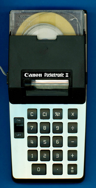
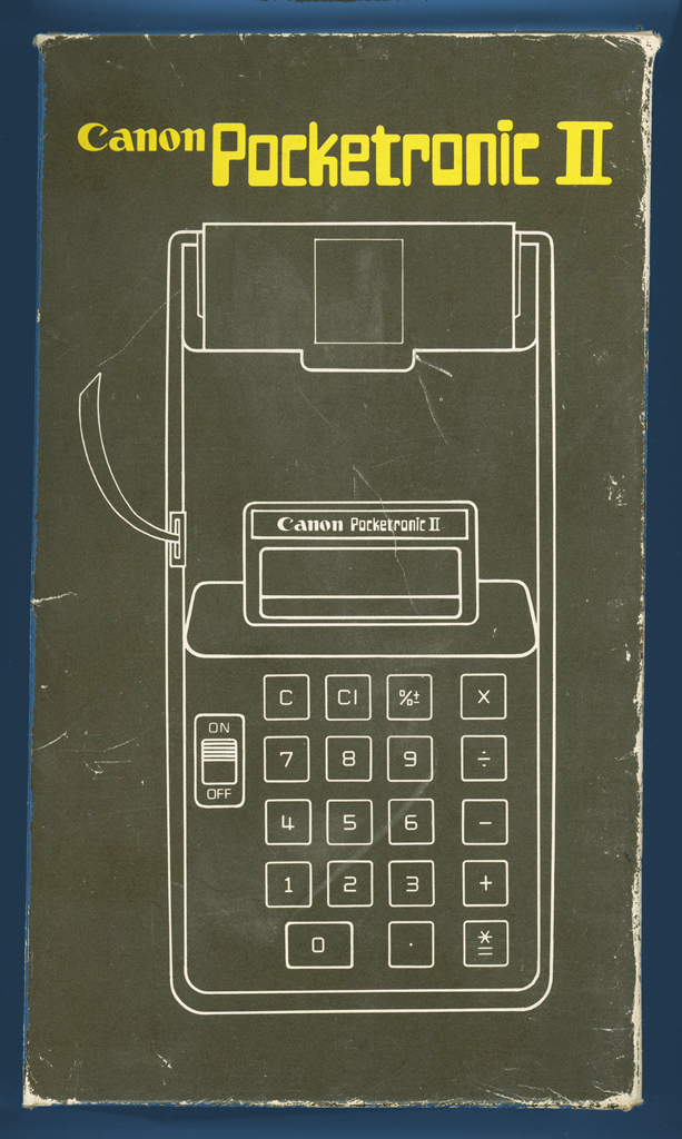
Canon Pocketronic II
| Date of introduction: | July 1974 | Display technology: | |
| New price: | Display size: | n.a. | |
| Size: | 2.3" x 3.7" x
0.20" 200 x 103 x 53 mm3 |
Printer technology: | Thermal |
| Weight: | 1.6 ounces, 654 grams | Serial No: | 120557 |
| Batteries: | 11*NiCd AA | Date of manufacture: | mth 08 year 1974 |
| AC-Adapter: | Canon CH-1 | Origin of manufacture: | USA |
| Precision: | 10 | Integrated circuits: | TMC0138, TMS0641 |
| Memories: | |||
| Program steps: | Courtesy of: | Joerg Woerner | |
| Download manual: | |
![]()
 Canon
Inc. of Japan introduced this Pocketronic II Printing Calculator as successor of the famous Pocketronic,
the impressive outcome of Texas Instruments' revolutionary Cal-Tech
project.
Canon
Inc. of Japan introduced this Pocketronic II Printing Calculator as successor of the famous Pocketronic,
the impressive outcome of Texas Instruments' revolutionary Cal-Tech
project.
The main difference between the original Pocketronic
introduced already in April 1970 and its sequel are the squeezed
electronics, the three MOS/LSI (Metal-oxide Semiconductor/Large-scale
Integration) chips of the Pocketronic were replaced
with an TMC0138 single-chip calculator
circuit and an additional integrated circuit to control the serial printing
mechanism and printer head.
While the
TMS0100 Family was designed to support all popular display technologies like Vacuum
Fluorescent Displays (VFD),
Light-emitting Diode (LED)
Displays, cold cathode
Panaplex Displays and even Liquid-crystal Displays (LCD),
lacks the Pocketronic II still any display. Casio's
mini-printer introduced about 6 months
after the Pocketronic II combined a serial printer with an 8-digit LED display.
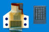
 The
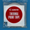
serial thermal printhead of the Pocketronic II with the 4x5 dot-matrix
arrangement of its heater elements is compatible with the original Pocketronic
and both calculators are using identical cartridges for the thermal paper tape.
The
serial thermal printhead of the Pocketronic II with the 4x5 dot-matrix
arrangement of its heater elements is compatible with the original Pocketronic
and both calculators are using identical cartridges for the thermal paper tape.
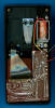
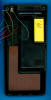
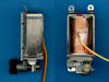
 Disassembling the featured Pocketronic II manufactured in August 1974 by
Canon in the United States reveals a well engineered and cost-optimized design
in an arrangement similar to the original Pocketronic. The Pocketronic II uses a
total of 11 AA-sized rechargable NiCd batteries while the original Pocketronic
was using a mix of 6 AA-sized and 7 smaller 2/3 AA-sized NiCd batteries. Other
components like the locking mechanism for the thermal paper tape cartridge, the
electromagnetic actuator with its rachet mechanism to transport the paper tape
and the printhead itself look like a carry-over from the original design.
Disassembling the featured Pocketronic II manufactured in August 1974 by
Canon in the United States reveals a well engineered and cost-optimized design
in an arrangement similar to the original Pocketronic. The Pocketronic II uses a
total of 11 AA-sized rechargable NiCd batteries while the original Pocketronic
was using a mix of 6 AA-sized and 7 smaller 2/3 AA-sized NiCd batteries. Other
components like the locking mechanism for the thermal paper tape cartridge, the
electromagnetic actuator with its rachet mechanism to transport the paper tape
and the printhead itself look like a carry-over from the original design.
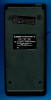
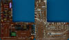
 Removing the Main printed circuit board (PCB) of the Pocketronic II shows
immediately the progress in chip manufacturing technology predicted already in
1965 by Gordon E. Moore - co-founder of Intel - and today known as "Moore's
Law". The complex arrangement of the three MOS/LSI Chips TMC1730, TMC1731
and TMC1732 making up the calculator brain of the Pocketronic was replaced with a
TMC0138 single-chip calculator circuit from the TMS0100 Family.
Removing the Main printed circuit board (PCB) of the Pocketronic II shows
immediately the progress in chip manufacturing technology predicted already in
1965 by Gordon E. Moore - co-founder of Intel - and today known as "Moore's
Law". The complex arrangement of the three MOS/LSI Chips TMC1730, TMC1731
and TMC1732 making up the calculator brain of the Pocketronic was replaced with a
TMC0138 single-chip calculator circuit from the TMS0100 Family.
![]() While
the TMS0100 was a huge step towards affordable portable, electronic calculators
did it not support TI’s first own display technology, the serial thermal
printer. This created most likely a headache with Canon’s Product Manager
responsible for the Pocketronic II.
While
the TMS0100 was a huge step towards affordable portable, electronic calculators
did it not support TI’s first own display technology, the serial thermal
printer. This created most likely a headache with Canon’s Product Manager
responsible for the Pocketronic II.
![]() Texas Instruments filled the void with the
TMS0640 Printer Chip as a peripheral device for the TMS0100 single-chip calculator and supporting the original Pocketronic
4x5 dot-matrix serial thermal printer head. It is clearly a contradiction to add a Printer Chip to a
"calculator-on-a-chip" for a two-chip design, but Texas Instrument was already used to the
TMS0200 Building Blocks for Desktop Calculators featuring with the
TMS0220 Printer Chip for a two-color Drum Printer and the
TMC0250 Printer/Display Chip for parallel Thermal Printers, best known from the Printer Cradle
PC-100 introduced with the
SR-52 Programmable Calculator. While the TMS0200 Building Blocks used a flexible, modular architecture that could be arranged like Lego blocks to achieve the desired calculator functionality, was the TMS0100 single-chip calculator designed to operate solely with digit-scanned displays and featured no
"communication interface" to peripheral devices.
Texas Instruments filled the void with the
TMS0640 Printer Chip as a peripheral device for the TMS0100 single-chip calculator and supporting the original Pocketronic
4x5 dot-matrix serial thermal printer head. It is clearly a contradiction to add a Printer Chip to a
"calculator-on-a-chip" for a two-chip design, but Texas Instrument was already used to the
TMS0200 Building Blocks for Desktop Calculators featuring with the
TMS0220 Printer Chip for a two-color Drum Printer and the
TMC0250 Printer/Display Chip for parallel Thermal Printers, best known from the Printer Cradle
PC-100 introduced with the
SR-52 Programmable Calculator. While the TMS0200 Building Blocks used a flexible, modular architecture that could be arranged like Lego blocks to achieve the desired calculator functionality, was the TMS0100 single-chip calculator designed to operate solely with digit-scanned displays and featured no
"communication interface" to peripheral devices.
Texas Instruments overcame these limitations with a rather complex design with the TMS0640 Printer Chip
"sniffing" into the internal operation of the TMS0100 Calculator Chip and even listening to the [C] key of the calculator. To allow this unusual approach, the TMS0641
(a mask-programmed version of the TMS0640 Printer Chip) generates the Clock Signal for the TMC0138,
actually a
TMS0700 single-chip calculator circuit specifically programmed for the Canon Pocketronic II, and synchronizes its own State Counter and Digit Counter to the TMC0138 by tapping into the S8 signal provided on Segment Output E and the Digit Output D2. Having the TMS0641 used with the Canon Pocketronic II operating now perfectly synchronous with the TMC0138, the Printer Chip receives the Numerals from the Calculator Chip in a modified Binary Coded Decimal (BCD) format through the four Segment Outputs SA, SB, SC, and SD. Other symbols like the +, −, and % sign or commands like Print are transferred serially with Segment Output SF as so-called Flag Bits. The Decimal Point information is received directly from the corresponding Segment Output SP while the [C] key is sampled by the TMS0640 Printer Chip during Digit Time D11 on the Keyboard Matrix Input KO. The otherwise unused Keyboard Matrix Input KQ of the Calculator Chip is connected to the Ready Output of the Printer Chip and sampled at Digit Time D10.
The TMS0640 Printer Chip uses two separate 13-digit registers to store the received numeric data from the Calculator Chip, the first one acts as an Input Register while the second one is used as Buffer Register during the serial printing of the numbers. A second set of smaller registers is used for the Flag Bits Data, namely a 4-bit register for the various symbols used with the Canon Pocketronic II and a 2-bit register for the print commands.
 The print control logic cycles through the various registers and uses an integrated character generator storing the font of a maximum of 25 numbers and symbols in a 5x5 dot-matrix arrangement to activate the heater elements of the serial thermal printhead accordingly. Texas Instruments offered for the TMS0640 a 5x5 heater array with the designation EPN2500 but the Canon Pocketronic II makes use of just a 4x5 heater subarray for its printhead.
 While the TMS0640 supports the control of a four-phase stepper motor, uses the Pocketronic II a much simpler electromagnetic actuator with a ratchet mechanism to move the paper horizontally in front of the printhead.
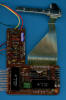
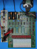 Preparing our DCM-50A Platform
to allow the Characterization of Single-Chip Calculator Circuits
of the TMS0100 Family, we studied
this Pocketronic II calculator manufactured in August 1974 and even developed an
Arduino-based debug setup for Recording the communication between the TMC0138 single-chip
calculator circuit and the TMS0641 Printer Chip.
Preparing our DCM-50A Platform
to allow the Characterization of Single-Chip Calculator Circuits
of the TMS0100 Family, we studied
this Pocketronic II calculator manufactured in August 1974 and even developed an
Arduino-based debug setup for Recording the communication between the TMC0138 single-chip
calculator circuit and the TMS0641 Printer Chip.
Learn more about Texas Instruments' approach to keep the print contrast of the serial thermal printer constant over the large temperature range from 0 °C to 40 °C (32 °F to 104 °F) of the Canon Pocketronic II, the Data and Command Interface between the TMC0138 and the TMS0641 and have a closer look at the character generator of the Printer Chip.
If you have additions to the above article please email: joerg@datamath.org.
© Joerg Woerner, December 5, 2001. No reprints without written permission.