DATAMATH CALCULATOR MUSEUM
|
DATAMATH CALCULATOR MUSEUM |
With the TMS1802NC Texas Instruments announced on September 17, 1971 the first available standard calculator building block on a chip, it was later renamed into TMS0102. The chip integrates 3520-bit Read-Only program memory, a 182-bit Serial-Access memory and a decimal arithmetic logic unit as well as control, timing, and output decoders but no drivers for the display. This gives an overall complexity of roughly 5,000 transistors.
Gordon Moore, the co-founder of Fairchild Semiconductor and Intel predicted already in 1965 that the numbers of transistors in Large-scale Integration (LSI) chips would double every year for the next 10 years. In 1975, looking forward to the next decade, he revised the forecast to doubling every two years, a compound annual growth rate (CAGR) of 41%. While Moore did not use empirical evidence in forecasting that the historical trend would continue, his prediction held since 1975 and has since become known as a "law". Main enablers were and are a combination of both reducing the size of the individual components (process shrink) and increasing the chip size (yield improvement). The manufacturing costs of an Integrated Circuit (IC) are calculated with:
|
• IC cost = (Die cost + Testing cost + Packaging cost) / Final test yield |
 With the die cost roughly proportional to the die area, testing and packaging costs roughly proportional to the pin count, and the final test yield mostly inverse proportional to the die area, goals are well defined: Keep the die size as small as possible for a set of requirements agreed on. With both ROM (Read-Only Memory) and RWM (Read-Write Memory) sizes the main contributors to the die area
of a single-chip calculator circuit and shift-register based data memory (SAM,
Serial-Access Memory) of Register Processors denser than RAM (Random-Access Memory) of Digit Processors, Texas Instruments
expanded the TMS0100 Product Family two years after its introduction into three
different branches:
With the die cost roughly proportional to the die area, testing and packaging costs roughly proportional to the pin count, and the final test yield mostly inverse proportional to the die area, goals are well defined: Keep the die size as small as possible for a set of requirements agreed on. With both ROM (Read-Only Memory) and RWM (Read-Write Memory) sizes the main contributors to the die area
of a single-chip calculator circuit and shift-register based data memory (SAM,
Serial-Access Memory) of Register Processors denser than RAM (Random-Access Memory) of Digit Processors, Texas Instruments
expanded the TMS0100 Product Family two years after its introduction into three
different branches:
|
• TMS0600: Increased ROM (384 Words
* 11 Bits), Identical SAM (13 Digits Registers), external display drivers. Process shrink, higher functionality • TMS0700: Identical ROM (320 Words * 11 Bits), Identical SAM (13 Digits Registers), external display drivers. Process shrink, identical functionality, cost reduction of IC • TMS0800: Identical ROM (320 Words * 11 Bits), Reduced SAM (11 Digits Registers), integrated segment drivers. Process shrink, reduced functionality, higher integration |
Please notice that the members of the TMS0700 Product Family were still marketed and marked as TMS0100 but both the die and the bottom of the chip package usually sport a TMS0700 marking.
Due to a flexible design concept of the TMS0700 architecture with both programmable PLA and ROM techniques a lot of design variations appeared. These include two different types of the key-matrix, 8 or 10 digits of 7- or 8-segmented outputs. The polarity of the segment output can be programmed. Some displays such as LCD (Liquid-Crystal-Display) are easier to interface with inverted polarity. The blanking of the segments is also programmable within limits to facilitate the interface with certain displays such as Panaplex™. Even the style of the numbers 6, 7 and 9 varied among the family members.
Based on the experience of the TMS0120 developed for the SR-10 some fully floating-point devices derived from the TMS0106 were developed:
| Features/ Device |
[+=] [−=] |
[+] [−] [=] |
[×] [÷] | [+/−] | [C] [CE] | [CONST] | [0-9/F] | [EE] | [1/x] | [x2] | [√x] | [%] [‰] | [A/D] [00] | [pi] | Memory | Display Format |
| TMS0720 | * | * | * | * | * | * | * | * | E88888888-88 | |||||||
| TMS0723 | * | * | * | * | * | * | * | E8888888888 | ||||||||
| TMS0726 | * | * | * | * | * | * | * | E88888888 | ||||||||
| TMS0727 | * | * | * | * | * | * | * | * | E8888888888 | |||||||
| TMS0728 | * | * | * | * | * | * | * | * | E88888888 | |||||||
| TMS0730 | * | * | * | * | * | * | E88888888 | |||||||||
| TMS0731 | * | * | * | * | * | E88888888 | ||||||||||
| TMS0732 | * | * | * | * | * | * | E88888888 | |||||||||
| TMS0737 | * | * | * | * | * | E88888888 | ||||||||||
| TMC0738 | * | * | * | * | * | Uses TMS0641 |
| Type | Calculators | Keyboard | Constant (M-D-A-S) |
Digits | Fixed DP | Rounding | Special Functions |
Seg./Dig. Blanking |
(6,7,9) Font |
Seg. H | Entry Overflow |
Calculating Overflow |
Pref. Type |
| TMS0101 | Canon Palmtronic LE-80, LE-83 | [+][−][=] | 1-2-X-X | 8 | 0-7, F | DOWN | NONE S1, S13 |
YES | |||||
| TMS0102 | Columbia II | [+=][−=] | 1/2 | 8 | 0-7, F | 5/4 | NONE S1, S13 |
||||||
| TMS0103 | Bowmar 901B, JCE Mark II, Montgomery Ward P800, P8F | [+=][−=] | 1/2 | 8 | 0-7, F | 5/4 | NONE S1, S13 |
YES | |||||
| TMS0105 | Canon L800, Panasonic JE-801A, Privileg 2000 | [+=][−=] | 1/2 | 8 | 0-7, F | 5/4 | NONE S1, S13 |
||||||
| TMS0106 | TI-3500, Canon L100S, Radio Shack EC-2000 | [+=][−=] | 1/2 | 10 | 0-9, F | 3-POS | S1, S13 S1, S13 |
YES | |||||
| TMS0107 | Bowmar 901D | [+=][−=] | 1/2 | 10 | 0-9, F | 3-POS | S1, S13 S1, S13 |
||||||
| TMS0109 | TI-3000, Montgomery Ward P800, D8F, Radio Shack EC-1000 | [+=][−=] | 1/2 | 8 | 0-7, F | 5/4 | S1, S13 S1, S13 |
||||||
| TMS0112 | Toshiba BC-0801B, BC-802B | [+=][−=] | 1/2 | 8 | 0-7, F | 3-POS | NONE S1, S13 |
||||||
| TMS0115 | Olympia CD80, Panasonic JE-850 | [+][−][=] | 1/2 | 8 | Float | NONE | S1, S13 S1, S13 |
||||||
| TMS0117 | BCD Coprocessor | 10 | BCD Output | (Note 1) | |||||||||
| TMS0118 | [+][−][=] | 2/2 | 10 | 0-9, F | 3-POS | S1, S13 S1, S13 |
YES | ||||||
| TMS0119 | TI-2500, Heathkit IC-2108 | [+][−][=] | 2/2 | 8 | 0-7, F | DOWN | NONE S1, S13 |
||||||
| TMS0120 | SR-10, Montgomery Ward P300, Radio Shack EC-425 | [+][−][=] | 8+2 | Float | NONE | [EE][1/x] [x2][√x] |
NONE NONE |
||||||
| TMS0121 | Olympia CD101, Panasonic JE-1001 | [+][−][=] | 1/2 | 10 | 0-9, F | DOWN, 5/4 | [X<>Y] | NONE S1, S13 |
|||||
| TMS0122 | Olympia CD80, Panasonic JE-850 | [+][−][=] | 1/2 | 8 | Float | NONE | S1, S13 S1, S13 |
||||||
| TMS0123 | Hunor 103 | [+=][−=] | 1/2 | 10 | Float | NONE | [x2][√x] | S1, S13 S1, S13 |
YES | ||||
| TMS0125 | Canon Palmtronic LE-100 | [+][−][=] | 10 | 0-9, F | DOWN | S1, S13 S1, S13 |
|||||||
| TMS0126 | Canon LE-80R, Casio ROOT-8S, Commodore 3101, Kings Point EC-8413, Privileg 820 | [+=][−=] | 1/2 | 8 | Float | NONE | [x2][√x] | NONE S1, S13 |
YES | ||||
| TMS0127 | Bowmar MX-80, Canon L1000 | [+=][−=] | 1/2 | 10 | 0-9, F | 5/4 | [A/D][%] [‰][00] |
S1, S13 S1, S13 |
YES | ||||
| TMS0128 | Canon LE-82, Interton PC 2008, JCE Percent, Montgomery Ward P8P, Western Auto M4995 | [+=][−=] | 1/2 | 8 | 0-7, F | 5/4 | [A/D][%] [‰][00] |
S1, S13 S1, S13 |
YES | ||||
| TMS0130 | Olympia CD85, Panasonic JE-860 | [+][−][=] | 8 | [√x][PI] | |||||||||
| TMS0131 | Olympia CD81, Panasonic JE-835, JE-855 | [+][−][=] | 8 | Memory | |||||||||
| TMS0132 | APF Mark VII,
Commodore MM3MT, Craig
4510, Hunor 88, Unico H-854 |
[+=][−=] | 8 | Memory | |||||||||
| TMS0135 | Exactra 20, TI-2000 | [+][−][=] | 6 | 0-5, F | |||||||||
| TMS0137 | Sears 8 | [+][−][=] | 8 | [%] | |||||||||
| TMC0138 | Canon Pocketronic II | [+][−][=] | 10 | [%] | (Note 2) S1, S13 |
(Note 3) | |||||||
| TMS0719 | TI-2500 | [+][−][=] | 2/2 | 8 | 0-7, F | DOWN | NONE S1, S13 |
| Description | Comments | |
| Architecture | Single-chip Calculator | First Generation |
| Category | Register Processor | BCD-serial |
| Related |
TMS0600 TMS0800 |
Larger
ROM Integrated Segment Drivers |
| ROM Size | 3,520 Bits | 320 Words * 11 Bits |
| RAM Size | 182 Bits | 3 Registers * 13 Digits, 2 * 13 Bit-Flags |
| Outputs | 11 Digits 9 Segments |
External Digit Drivers Internal Segment Drivers |
| Inputs | 4 Keyboard 0 Miscellaneous |
Digit to Keyboard Scan-Matrix |
The Datamath Calculator Museum DCM-50A (Platform) supports the TMS0700 Product Family with its left-most TMS0100 Textool Test Socket set to DCM-50A (TMS0100) mode. Both Characterization of TMS0700 Calculator Circuits and Reverse-engineering of TMS0700 Calculator Circuits is supported by the DCM-50A (TMS0100).
| Item | Min | Typ | Max | Unit | Comments |
| VSS | 0 | V | |||
| VDD | -8.1 | -7.2 | -6.6 | V | |
| VGG | -16.2 | -14.4 | -13.2 | V | |
| IDD | 17 | 25 | mA | ||
| IGG | 10 | 15 | mA | ||
| CK | 100 | 250 | 400 | kHz | Level between VSS and VGG |
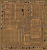
The TMS0700 was manufactured in a 8 um metal gate PMOS process (metal width = 0.30 mil / 8.0 um, metal spacing = 0.35 mil / 9.0 um, diffusion width = 0.25 mil / 6.0 um, diffusion spacing = 0.35 mil / 9.0 um).
The die size of the TMS0700 is approximately 200 mils * 210 mils / 5.0 mm * 5.3 mm.
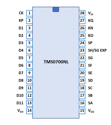
The TMS0700 uses a standard 0.6” wide 28-pin DIP (Dual In-line Package with a 0.1” / 2.54 mm lead pitch).
| Pin | IO | Function | Pin | IO | Function |
| 1 | I | Clock Input | 28 | V | Common Voltage |
| 2 | I | Keymatrix input P | 27 | I | Keymatrix input Q |
| 3 | O | Digit driver 1 (LSD) | 26 | I | Keymatrix input N |
| 4 | O | Digit driver 2 | 25 | I | Keymatrix input O |
| 5 | O | Digit driver 3 | 24 | O | Segment driver DP |
| 6 | O | Digit driver 4 | 23 | O | Segment driver H/G (EXP) |
| 7 | O | Digit driver 5 | 22 | O | Segment driver G |
| 8 | O | Digit driver 6 | 21 | O | Segment driver F |
| 9 | O | Digit driver 7 | 20 | O | Segment driver E |
| 10 | O | Digit driver 8 (MSD8) | 19 | O | Segment driver D |
| 11 | O | Digit driver 9 | 18 | O | Segment driver C |
| 12 | O | Digit driver 10 (MSD10) | 17 | O | Segment driver B |
| 13 | O | Digit driver 11 (OVER) | 16 | O | Segment driver A |
| 14 | V | Negative Voltage VDD | 15 | V | Negative Voltage VGG |
| The Segment drivers A-G/H and DP (Decimal Point) are connected to the display in the pictured way. | 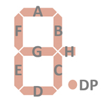 |
| The Segment drivers A-G/H and DP (Decimal Point) are connected to the display in the pictured way. The TMS0720 repurposes the Segment H for the minus sign of the Exponent in the pictured way. | 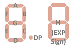 |
The keyboards of all calculators based on the TMS0700 Product Family consist of a x/y-matrix connected to the digit driver outputs D1-D11 and the keymatrix inputs KN (Numbers) and KO (Operations). In the fixed-point output format mode the position of the decimal point is selected with the KP (Decimal Point) input. The Constant/Chain switch is connected between D10-KQ (Constant).
Scanning is performed in D11 → D1 direction at a rate of about 584 Hz:
|
• State Time = 3 Clocks =
0.012 ms @ CK=250 kHz • Digit Time = 13 States (1 Instruction Cycle) = 0.156 ms @ CK=250 kHz • Scan Time = 11 Digit Times (D1 to D11) = 1.712 ms @ CK=250 kHz |
TMS0702, 0703, 0705, 0709 |
TMS0701 |
||||||||
| KN | KO | KP | KQ | KN | KO | KP | KQ | ||
| D1 | 1 | DP1 | D1 | 1 | + | DP1 | |||
| D2 | 2 | × | DP2 | D2 | 2 | × | DP2 | ||
| D3 | 3 | ÷ | DP3 | D3 | 3 | ÷ | DP3 | ||
| D4 | 4 | DP4 | D4 | 4 | − | DP4 | |||
| D5 | 5 | += | DP5 | D5 | 5 | DP5 | |||
| D6 | 6 | −= | DP6 | D6 | 6 | DP6 | |||
| D7 | 7 | +/− | DP7 | D7 | 7 | +/− | DP7 | ||
| D8 | 8 | D8 | 8 | = | |||||
| D9 | 9 | . | D9 | 9 | . | ||||
| D10 | 0 | CE | DP0 | K | D10 | 0 | CE | DP0 | K |
| D11 | C | D11 | C | ||||||
TMS0706 |
TMS0707 |
||||||||
| KN | KO | KP | KQ | KN | KO | KP | KQ | ||
| D1 | 1 | DP1 | D1 | 1 | DP1 | ||||
| D2 | 2 | × | DP2 | D2 | 2 | × | DP2 | ||
| D3 | 3 | ÷ | DP3 | D3 | 3 | ÷ | DP3 | ||
| D4 | 4 | DP4 | D4 | 4 | DP4 | ||||
| D5 | 5 | += | DP5 | D5 | 5 | += | DP5 | ||
| D6 | 6 | −= | DP6 | D6 | 6 | −= | DP6 | ||
| D7 | 7 | +/− | DP7 | 5/4 | D7 | 7 | +/− | DP7 | UP |
| D8 | 8 | DP8 | D8 | 8 | DP8 | ||||
| D9 | 9 | . | DP9 | DWN | D9 | 9 | . | DP9 | DWN |
| D10 | 0 | CE | DP0 | K | D10 | 0 | CE | DP0 | K |
| D11 | C | D11 | C | ||||||
TMS0718 |
TMS0720 |
||||||||
| KN | KO | KP | KQ | KN | KO | KP | KQ | ||
| D1 | 1 | + | DP1 | D1 | 9 | − | |||
| D2 | 2 | × | DP2 | D2 | 8 | + | |||
| D3 | 3 | ÷ | DP3 | D3 | 7 | × | |||
| D4 | 4 | − | DP4 | D4 | 6 | ÷ | √x | ||
| D5 | 5 | DP5 | D5 | 5 | CD | ||||
| D6 | 6 | DP6 | D6 | 4 | EE | 1/x | |||
| D7 | 7 | +/− | DP7 | 5/4 | D7 | 3 | +/− | ||
| D8 | 8 | = | DP8 | D8 | 2 | = | x2 | ||
| D9 | 9 | . | DP9 | DWN | D9 | 1 | . | ||
| D10 | 0 | CE | DP0 | K | D10 | 0 | |||
| D11 | C | D11 | C | ||||||
TMS0721 |
|
||||||||
| KN | KO | KP | KQ | KN | KO | KP | KQ | ||
| D1 | 1 | + | DP1 | D1 | |||||
| D2 | 2 | × | DP2 | D2 | |||||
| D3 | 3 | ÷ | DP3 | D3 | |||||
| D4 | 4 | − | DP4 | D4 | |||||
| D5 | 5 | DP5 | D5 | ||||||
| D6 | 6 | DP6 | D6 | ||||||
| D7 | 7 | X<>Y | DP7 | D7 | |||||
| D8 | 8 | = | DP8 | D8 | |||||
| D9 | 9 | . | DP9 | D9 | |||||
| D10 | 0 | CE | DP0 | 5/4 | D10 | ||||
| D11 | C | D11 | |||||||
TMS0723, 0726 |
TMS0727 (*), 0728 |
||||||||
| KN | KO | KP | KQ | KN | KO | KP | KQ | ||
| D1 | 1 | x2 | D1 | 1 | ‰ | DP1 | |||
| D2 | 2 | × | D2 | 2 | × | DP2 | |||
| D3 | 3 | ÷ | D3 | 3 | ÷ | DP3 | |||
| D4 | 4 | √x | D4 | 4 | % | DP4 | |||
| D5 | 5 | += | D5 | 5 | += | DP5 | |||
| D6 | 6 | −= | D6 | 6 | −= | DP6 | |||
| D7 | 7 | +/− | D7 | 7 | 00 | DP7 | |||
| D8 | 8 | D8 | 8 | A/D | DP8(*) | ||||
| D9 | 9 | . | D9 | 9 | . | DP9(*) | |||
| D10 | 0 | CE | K | D10 | 0 | CE | DP0 | K | |
| D11 | C | D11 | C | ||||||
TMC0738 |
||||
| KN | KO | KP | KQ | |
| D1 | 1 | + | ||
| D2 | 2 | × | ||
| D3 | 3 | ÷ | ||
| D4 | 4 | − | ||
| D5 | 5 | |||
| D6 | 6 | |||
| D7 | 7 | %+/− | ||
| D8 | 8 | = | ||
| D9 | 9 | . | ||
| D10 | 0 | CI | [RDY] | |
| D11 | C | |||
Calculators based on the TMS0700 use all kinds of displays including but not limited to LED (Light-Emitting-Diode), Panaplex™ (Gas-Discharge-Display), and low-voltage VFD (Vacuum-Fluorescent-Display) technology.
If you have additions to the above datasheet please email: joerg@datamath.org.
© Joerg Woerner, July 12, 2021. No reprints
without written permission.