DATAMATH CALCULATOR MUSEUM
|
DATAMATH CALCULATOR MUSEUM |
When Texas Instruments started in Fall 1965 the Cal-Tech project to demonstrate the use of MOS/LSI (Metal-oxide Semiconductor/Large-scale Integration) technology in consumer-grade products, display technology was still in its infancy. The only available technology used mainly in industrial-grade products like Digital Voltmeters or Frequency Counters was the cold cathode display or Nixie tube introduced in 1955 and making its way into the large, transistorized desktop calculators appearing in 1964 on the market. Texas Instruments consequently developed for the Cal-Tech project with a serial thermal printer a novel display technology and completed its first prototypes of a battery powered hand-held calculator in 1967. The prototype calculator was shown to various business machine manufacturers and Canon became very interested in the new technology. When Canon introduced in 1970 with the Pocketronic their first portable electronic calculator, it unsurprisingly incorporated the unique thermal printing tape system known from the Cal-Tech prototype and supplied by Texas Instruments.
In the five years between TI’s decision to incorporate a thermal printer in the Cal-Tech project and the introduction of Canon’s Pocketronic in Spring 1970, display technology for portable products made huge successes. ISE Electronics Corporation invented in 1967 the Vacuum Fluorescent Display (VFD), RCA Laboratories demonstrated in 1968 the first Liquid-crystal Display (LCD), Monsanto introduced in 1969 with the MAN-1A the World’s first 7-segment Light-emitting Diode (LED) Display and RCA started in 1979 selling with their Numitrons a 7-segment Display based on incandescent elements before Burroughs introduced with their Panaplex Display a flat, more compact version of the cold cathode principle known from the ancient Nixie tubes.
It was certainly a surprise to learn that Sanyo Electronics Company’s first "Mini Calculator", the IC-82D introduced in May 1970 cramped 8 Nixie tubes into a portable product while Sharp Corporation was betting with their desktop calculator QT-8D on Itron’s VF Display.
When Texas Instruments announced in September 1971 with the TMS1802 the World’s first "calculator-on-a-chip", the "Battle of Displays" was already fully engulfed, and the calculator chip was accordingly designed to be used with most popular displays. The display outputs of the TMS1802, later renamed to TMS0102 and the first member of the highly popular TMS0100 Family, are fully decoded, include programmable inter-digit blanking and have programmable polarity. While all (Note) known calculator designs based on the TMS0100 Family incorporate 7-Segment or 8-Segment decoders, featured the early calculator chips even two spare pads for Nixie tubes on the silicon die that were not bonded to pins of the 28-pin chip package.
(Note: Texas Instruments sold with the TMS0117 a "Number Cruncher" based on the TMS0100 and meant to be used as a peripheral device for computers, that outputs 4-bit Binary Coded Decimal data.)While the TMS0100 was a huge step towards affordable portable, electronic calculators did it not support TI’s first own display technology, the serial thermal printer. This created most likely a headache with Canon’s Product Manager responsible for the successor of the Pocketronic, consequently named Pocketronic II.
Texas Instruments filled the void with the TMS0640 Printer Chip as a peripheral device for the TMS0100 single-chip calculator and supporting the original Pocketronic 4x5 dot-matrix serial thermal printer head. It is clearly a contradiction to add a Printer Chip to a "calculator-on-a-chip" for a two-chip design, but Texas Instrument was already used to the TMS0200 Building Blocks for Desktop Calculators featuring with the TMS0220 Printer Chip for a two-color Drum Printer and the TMC0250 Printer/Display Chip for parallel Thermal Printers, best known from the Printer Cradle PC-100 introduced with the SR-52 Programmable Calculator. While the TMS0200 Building Blocks used a flexible, modular architecture that could be arranged like Lego blocks to achieve the desired calculator functionality, was the TMS0100 single-chip calculator designed to operate solely with digit-scanned displays and featured no "communication interface" to peripheral devices.
Texas Instruments overcame these limitations with a rather complex design with the TMS0640 Printer Chip "sniffing" into the internal operation of the TMS0100 Calculator Chip and even listening to the [C] key of the calculator. To allow this unusual approach, the TMS0640 generates the Clock Signal for the TMC0138, actually a TMS0700 single-chip calculator circuit specifically programmed for the Canon Pocketronic II, and synchronizes its own State Counter and Digit Counter to the TMC0138 by tapping into the S8 signal provided on Segment Output E and the Digit Output D2. Having the TMS0641 used with the Canon Pocketronic II operating now perfectly synchronous with the TMC0138, the Printer Chip receives the Numerals from the Calculator Chip in a modified Binary Coded Decimal (BCD) format through the four Segment Outputs SA, SB, SC, and SD. Other symbols like the +, −, and % sign or commands like Print are transferred serially with Segment Output SF as so-called Flag Bits. The Decimal Point information is received directly from the corresponding Segment Output SP while the [C] key is sampled by the TMS0640 Printer Chip during Digit Time D11 on the Keyboard Matrix Input KO. The otherwise unused Keyboard Matrix Input KQ of the Calculator Chip is connected to the Ready Output of the Printer Chip and sampled at Digit Time D10.
The TMS0640 Printer Chip uses two separate 13-digit registers to store the received numeric data from the Calculator Chip, the first one acts as an Input Register while the second one is used as Buffer Register during the serial printing of the numbers. A second set of smaller registers is used for the Flag Bits Data, namely a 4-bit register for the various symbols used with the Canon Pocketronic II and a 2-bit register for the print commands.
The print control logic cycles through the various registers and uses an integrated character generator storing the font of a maximum of 25 numbers and symbols in a 5x5 dot-matrix arrangement to activate the heater elements of the serial thermal printhead accordingly. Texas Instruments offered for the TMS0640 a 5x5 heater array with the designation EPN2500 but the Canon Pocketronic II makes use of just a 4x5 heater subarray for its printhead.
While the TMS0640 supports the control of a four-phase stepper motor, uses the Pocketronic II a much simpler electromagnetic actuator with a ratchet mechanism to move the paper horizontally in front of the printhead.
QUICK-LINK to TMS0700 Family.
| Type | Calculators | Function |
| TMS0641 | Canon Pocketronic II | With TMC0138 |
| Item | Min | Typ | Max | Unit | Comments |
| VSS | 0 | V | |||
| VDD | -8.1 | -7.2 | -6.6 | V | |
| VGG | -16.2 | -14.4 | -13.2 | V | |
| IDD | tbd | tbd | mA | ||
| IGG | tbd | tbd | mA | ||
| CK | 100 | 250 | 400 | kHz | Level between VSS and VGG |
CLOCK GENERATOR
A critical aspect of thermal printers is reaching the correct temperature of the heater elements under fluctuating ambient conditions to achieve the best possible contrast of the printout. The Canon Pocketronic II using the TMS0641 Printer Chip is specified to operate over a large temperature range from 0 °C to 40 °C (32 °F to 104 °F) and using a constant voltage for the heater elements, their on-time needs to vary between typically 15 ms at lowest temperature and 5 ms at highest temperature. Texas Instruments chose to control the temperature-dependent on-time directly by modifying the clock frequency of both the Printer Chip and Calculator Chip with a so-called Negative Temperature Coefficient (NTC) Thermistor and added a potentiometer for fine-adjustment of the on-time during production of the calculator.
The TMS0641 Printer Chip of a Canon Pocketronic II manufactured in April 1974 uses four passive components for its oscillator:
|
• C1: 150 pF ceramic disc capacitor for integrated RC oscillator • RV1: 100 kOhm potentiometer for frequency adjustment (S = 100 kOhm, F = 0 Ohm) • R1: 33 kOhm resistor for RC oscillator • TH1: 33 kOhm NTC thermistor connected in series with R1 for RC oscillator |
NTC thermistors are usually specified at an ambient temperature of 25 °C, the selected 33k Ohm NTC would measure around 110 kOhm at 0 °C, 41k Ohm at 20 °C and 17 kOhm at 40 °C.
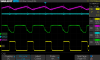
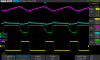
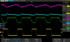 To better understand the influence of ambient temperature on the on-time of the printhead with the chosen components, we replaced the NTC thermistor of a Canon Pocketronic II with standard resistors and measured the clock frequency provided on the CK Output with the adjustment potentiometer in its center position, set to S (Slow) and set to F (Fast).
| CK Frequency (kHz) | NTC (0 °C) 110 kOhm |
NTC (20 °C) 41 kOhm |
NTC (40 °C) 17 kOhm |
| Poti (Fast) - 0 kOhm | 130 | 203 | 262 |
| Poti (Center) - 50 kOhm | 112 | 178 | 230 |
| Poti (Slow) - 100 kOhm | 95 | 154 | 200 |
The table above demonstrates that the temperature compensation of the oscillator frequency realized with the NTC thermistor covers about a ratio of 2:1 between the lowest and highest operating temperatures, effectively halving the on-time of the heater elements at 40 °C compared to 0 °C.
(Note: The CK Frequency of the RC Oscillator decreases slightly during
measurement with the Oscilloscope due to the additional capacitance of the
used probe)
The fine adjustment of the oscillator frequency with the potentiometer during production covers a much smaller range of about +/- 15% and is realized with modifying the hysteresis of the RC oscillator.
TIMING AND SYCHRONIZATION
The nominal clock frequency of the TMS0100 single-chip calculator circuit is 250 kHz and one State Time is equivalent to three clock pulses or 12 us. A Digit Time is equivalent to thirteen State Times or about 156 us and corresponds to one Instruction Cycle. Scanning of the keyboard and display of a calculator based on the TMS0100 chip takes 11 Digit Times and is performed in D11 → D10 → D1 → D11 order to allow for an easier implementation of its leading-zero suppression feature.
The TMS0640 Printer Chip is using two Input Signals to synchronize its internal State Counter and Digit Counter with the TMS0100 Calculator Chip:
|
• S8: Initiates a 7-bit Shift Register generating S9 → S10 → S11 → S12 → S13 → S1 → S2 • D2: Initiates a 3-bit Shift Register generating D1 → D11 → D10 |
While the TMS0100 Calculator Chips are usually programmed to generate an inter-digit blanking during States S1 and S13 to avoid ghosting effects of the calculator displays, exhibits the TMC0138 used with the Canon Pocketronic II on its Segment Output E - which is connected to the S8 Input of the TMS0641 – an inter-digit blanking during States S1 to S7 and S9 to S13, hence generating a short pulse during S8. The D2 Input of the TMS0641 is connected directly to the Digit Output D2 of the TMC0138.
DATA AND COMMAND INTERFACE
The TMS0640 Printer Chip is using different means to receive the relevant data and commands from a connected TMS0100 Calculator Chip with every keyboard and display scan cycle:
|
• The Keyboard Matrix Input K0 is sampled at Digit Time D11, representing the [C] button scanning of the TMC0138 to reset the TMS0641 • The Data Inputs A1, A2, A4 and A8 are receiving the Numerals in a modified BCD format from the corresponding Segment Outputs SA, SB, SC, and SD of the TMC0138 • The DP Input samples the position of the Decimal Point of the TMC0138 and is connected directly to its Segment Output SP • The FLAG Input is receiving serially 6 Flag Bits divided into 4 Bits for Symbol Information and 2 Bits for Commands from the Segment Output SF of the TMC0138 |
The Data Inputs A1 to A8 are using a modified Binary Coded Decimal (BCD) format to distinguish between a "printed Zero" and a "non-printed Zero" necessary for the desired leading-zero suppression functionality of the TMS0100 Calculator Chips. In addition to the Numerals 0 to 9 includes the Numerals encoding the [-] sign:
| Data Input A8 A4 A2 A1 |
Encoding |
| 0 0 0 0 | Non-printed Zero |
| 0 0 0 1 | One |
| 0 0 1 0 | Two |
| 0 0 1 1 | Three |
| 0 1 0 0 | Four |
| 0 1 0 1 | Five |
| 0 1 1 0 | Six |
| 0 1 1 1 | Seven |
| 1 0 0 0 | Eight |
| 1 0 0 1 | Nine |
| 1 1 1 0 | Minus |
| 1 1 1 1 | Printed Zero |
The DP Input is used to insert a decimal point at the right position into its 13-digit registers for the numeric information. While the TMS0100 Calculator Chips are programmed for displays using a right-hand decimal point, is the Canon Pocketronic II printing the decimal point between the digits.
The 6 Flag Bits FB1 to FB6 received during one complete keyboard and display scan cycle of the TMS0100 Calculator Chip are divided into a 4-bit Field encoded in Digit Times D5 to D2 to address different Symbols like the +, -, and % sign of the Character Generator and a 2-bit Field encoded in Digit Times D7 and D6 for the different Commands.
The TMS0641 Printer Chip used with the Canon Pocketronic II is using 9 of the possible 16 Symbols encoded with Flag Bits FB1 to FB4, while the US Patent Application US 3,909,626 assigned to Texas Instruments Incorporated references only 8 Symbols:
| Flag Bits B4 B3 B2 B1 |
Encoding Pocketronic II |
Encoding US Patent |
| 0 0 0 0 | . | Space |
| 0 0 0 1 | Space | |
| 0 0 1 0 | . | |
| 0 0 1 1 | Space | |
| 0 1 0 0 | Space | |
| 0 1 0 1 | Space | |
| 0 1 1 0 | Space | |
| 0 1 1 1 | Space | |
| 1 0 0 0 | % | |
| 1 0 0 1 | E | E |
| 1 0 1 0 | + | + |
| 1 0 1 1 | − | − |
| 1 1 0 0 | × | × |
| 1 1 0 1 | ÷ | ÷ |
| 1 1 1 0 | = | = |
| 1 1 1 1 | C | C |
The printing of a single number, symbol, space or complete buffer is controlled with the Flag Bits FB5 and FB6:
| Flag Bits FB2 FB1 |
Encoding |
| 0 0 | Don't move |
| 0 1 | Print LSD |
| 1 0 | Print Symbol If FB4 = 1, no Space; If FB4 = 0, one Space |
| 1 1 | Print All |
Tracing the Flag Bits transmitted by the TMC0138 Calculator Chip used with the Canon Pocketronic II during a simple calculation [1] [+] [2] [=] shows the following sequence
for the transmitted Flag Bits:
| Flag Bits FB6,FB5 |
Flag Bits FB4 - FB1 |
Frequency | Comment |
| 0 0 | 0 0 0 0 | IDLE | Waiting for Key Input |
| 0 1 | 0 0 0 0 | 1 | Print LSD (1) |
| 0 0 | 0 0 0 0 | IDLE | Waiting for Key Input |
| 0 0 | 0 0 1 0 | 1 | Transient |
| 0 0 | 1 0 1 0 | 1 | Transient |
| 1 1 | 1 0 1 0 | 1 | Print Symbol (+) |
| 0 0 | 1 0 1 0 | 16 | Waiting for Ready |
| 0 0 | 1 0 0 0 | IDLE | Waiting for Key Input |
| 0 1 | 1 0 0 0 | 1 | Print LSD (2) |
| 0 0 | 1 0 0 0 | IDLE | Waiting for Key Input |
| 0 0 | 1 1 1 0 | 2 | Transient |
| 1 0 | 1 1 1 0 | 1 | Print Symbol (=) |
| 0 0 | 1 1 1 0 | IDLE | Waiting for Key Input |
PRINT CONTROL LOGIC AND
CHARACTER GENERATOR
The character generator of the TMS0640 Printer Chip is using a Programmable Logic Array (PLA) to store the font of a maximum of 25 numbers and symbols in a 5x5 dot-matrix arrangement used to activate the heater elements of the serial thermal printhead accordingly.
Texas Instruments offered for the TMS0640 a 5x5 heater array with the designation EPN2500 but the Canon Pocketronic II makes use of just a 4x5 heater subarray for its printhead and consequently are only four Column Outputs C1 to C4 bonded out to the 28-pin package of its TMS0641. The five Row Outputs R1 to R5 are driven directly by a five-stage recirculating counter addressing both the character generator and thermal print head accordingly.
| Type | Calculator | Number Fonts | Decimal Separator |
Entry Overflow |
Calculating Overflow |
Minus | Symbols |
| TMS0641NC | Canon Pocketronic II |
|
MOTOR DRIVER
While the TMS0640 supports the control of a four-phase stepper motor, uses the Canon Pocketronic II a much simpler electromagnetic actuator with a ratchet mechanism to move the paper horizontally in front of the printhead. The TMS0641 does not bond out three of the four Motor Pulse signals MP1 to MP 4 for the four-phase stepper motor and uses only MP4 for the solenoid of the serial print mechanism. After each successful printing of a single number, symbol, or space the output MP4 is activated briefly to advance the thermal paper to the next printing position.
The TMS0640 was manufactured in a 8 um metal gate PMOS process (metal width = 0.30 mil / 8.0 um, metal spacing = 0.35 mil / 9.0 um, diffusion width = 0.25 mil / 6.0 um, diffusion spacing = 0.35 mil / 9.0 um).
The die size of the TMS0640 is approximately 165 mils * 190 mils / 4.2 mm * 4.8 mm.
The TMS0641 uses a standard 0.6” wide 28-pin DIP (Dual In-line Package with a 0.1” / 2.54 mm lead pitch).
| Pin | IO | Function | Pin | IO | Function |
| 1 | Not Connected | 28 | O | Row Driver R1 | |
| 2 | V | Negative Voltage VDD | 27 | O | Row Driver R2 |
| 3 | V | Negative Voltage VGG | 26 | O | Row Driver R3 |
| 4 | V | Common Voltage VSS | 25 | O | Row Driver R4 |
| 5 | O | Motor Output MP4 | 24 | O | Row Driver R5 |
| 6 | I | State Time Input S8 | 23 | O | Column Driver C1 |
| 7 | I | Flag Bits Input | 22 | O | Column Driver C2 |
| 8 | I | Digit Time Input D2 | 21 | O | Column Driver C3 |
| 9 | I | RC Oscillator Input | 20 | O | Column Driver C4 |
| 10 | I | Osc. Adjustment Input | 19 | I | Data Input A8 (MSB) |
| 11 | O | RC Oscillator Output | 18 | I | Data Input A4 |
| 12 | O | Clock Output | 17 | I | Data Input A2 |
| 13 | I | Clear Input | 16 | I | Data Input A1 (LSB) |
| 14 | I | Decimal Point Input | 15 | O | Ready Output |
Calculators based on the TMS0640 make use of the EPN2500 5x5 heater array or like the Canon Pocketronic II a subarray with a 4x5 heater elements.
If you have additions to the above datasheet please email: joerg@datamath.org.
© Joerg Woerner, April 13, 2024. No reprints
without written permission.