DATAMATH CALCULATOR MUSEUM
|
|
DATAMATH CALCULATOR MUSEUM |
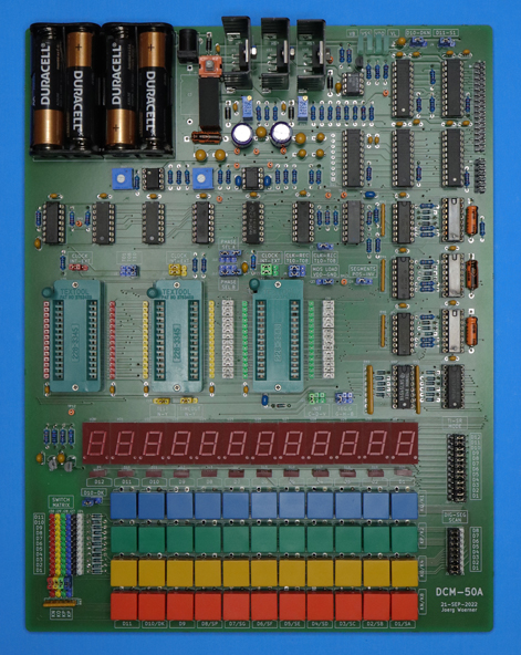
Datamath Calculator Museum DCM-50A (Platform)
| Date of introduction: | September 21, 2022 | Display technology: | LED |
| New price: | $849.95 (2022 = $119.95 in 1972) | Display size: | 12 |
| Size: | 10.5" x 8.5" x 1.5" 267 x 216 x 38 mm3 |
||
| Weight: | 17.4 ounces, 494 grams | Serial No: | 0001 |
| Batteries: | 4*AA | Date of manufacture: | mth 09 year 2022 |
| AC-Adapter: | DC 6V | Origin of manufacture: | USA |
| Precision: | Integrated circuits: | ZIF-Sockets for TMS0100, TMS0800, TMS1000, 3*SN75493, 2*SN75494 | |
| Memories: | Displays: | 12*HP 5082-7653 | |
| Program steps: | Courtesy of: | Joerg Woerner |
![]() So what is it all about this one-of-its-kind DCM-50A
Platform?
So what is it all about this one-of-its-kind DCM-50A
Platform?
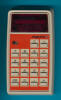
 Texas Instruments
introduced the
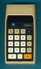
TI-2500 Datamath formally on September 21st, 1972 and here at the
Datamath Calculator Museum we celebrate the
50th Anniversary accordingly.
Texas Instruments
introduced the
TI-2500 Datamath formally on September 21st, 1972 and here at the
Datamath Calculator Museum we celebrate the
50th Anniversary accordingly.
When Texas Instruments invented with the TMS1802 – later renamed to TMS0102 - the single-chip calculator circuit and announced it on September 17th, 1971, they introduced a highly integrated device providing the following features:
| • Eight Digits • Four Operations • Three Registers • Floating-point or Fixed-point Operation (8 positions) • Constant or Chain Operation • Automatic Roundoff • Overflow Most Significant Digit Protection • Leading-zero Suppression • Internal Encoding of Keyboard Inputs • Decoded Display Outputs • Single-phase Clock • Automatic Power-up Clear |
 The chip was designed to operate with very few external components and connects to a switch matrix keyboard, features fully decoded segmented outputs and needs only simple drivers for the common display technologies. In hindsight most important characteristics of the TMS1802 was its groundbreaking architecture with most of the circuit designed using programming logic array (PLA) techniques, meaning that not only the calculator algorithm in the 320 Words Read-only Memory (ROM) could be defined with changing just a single photo mask in the manufacturing process, but allowing flexibility to adopt with the same manufacturing step:
| • Parts of the Instruction Set • Number of Digits, Leading-zero Suppression • Segment Decoder for 7-segment and 8-segment Displays with or w/o Serifs • Timing of the Segment and Digit Blanking to accommodate LED (Light Emitting Diode), VF (Vacuum Fluorescent), LC (Liquid Crystal), or Panaplex (Segmented Nixie Style) Displays |
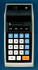
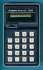
Texas Instruments marketed this first generation single-chip calculator circuit as TMS0100 family and the famous Bowmar 901B was based on the TMS0103 while the earliest TI-2500 Datamath, Minimath, TI-3000 Deskmath, and TI-3500 are using the TMS0110, TMS0111, TMS0109, and TMS0106, respectively. Even TI’s first "Slide Rule" calculator, the SR-10 introduced in November 1972 features with the TMS0120 a member of the TMS0100 family. Subsequent designs kept the overall architecture with just minor enhancements, paving the way for the TMS1000 Microcomputer introduced in October 1974 with the SR-16 and we know as of today:
| •
TMS0100: First generation single-chip calculator circuit • TMS0600: Larger program memory with 384 Words for more complex calculator algorithm, think TI-2550 or SR-11 • TMS0700: Design shrink of the TMS0100 chip for cost optimization, think Exactra 20 • TMS0800: Reduced Register size with 11 Digits Registers instead of 13 Digits Registers, integrated segment drivers and internal clock oscillator, think TI-1500 • TMS0830: Low-voltage process to operate on 9V battery, think MBO Expert • TMS0850: High-voltage drivers for VF-Displays, think Canon LD-80 • TMS1000: Switch from "Register Processor" to "Digit Processor" architecture to allow for non-arithmetic applications, think PC-800 • TMS0950: Cost reduced Digit Processor with integrated segment and display drivers. As a design consequence changing from digit-scanning of the keyboard matrix to segment-scanning. Think TI-1200 • TMS0970: Further cost-optimization with fully integrating clock oscillator and die-shrinking, think Little Professor |
The TMS1000 "computer-on-a-chip" grew in the Seventies into a large portfolio with different packages, ROM and RAM sizes, manufacturing processes or additional peripherals and could be considered the most successful 4-bit microcontroller enabling products like Texas Instruments’ very own Speak & Spell educational toy. Its architecture found its way into many later calculators, like the TI-30, TI-35 or TI-55-II.
With many of the single-chip calculator circuits either designed for Texas Instruments' proprietary applications or developed for OEM manufacturers, available documentation of their features is rather scarce and the Datamath Calculator Museum is committed to provide as much information as possible to the calculator enthusiasts and hence we designed the DCM-50A Platform.
Characterization of Single-chip Calculator Circuits
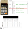
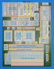
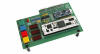
 Core idea of the DCM-50A design is providing a generic platform to access all features of a calculator based on Texas Instruments’ single-chip calculator circuits and the
schematics and layout of the printed circuit board features accordingly:
Core idea of the DCM-50A design is providing a generic platform to access all features of a calculator based on Texas Instruments’ single-chip calculator circuits and the
schematics and layout of the printed circuit board features accordingly:
| • Adjustable power supply rails for VSS (5.5V – 10.5V), VDD or VGG (-3.0V – -8.0V) and fixed supply voltage for LED display (5V) • Textool Test Socket for TMS0100, TMS0600, TMS0700 devices • Textool Test Socket for TMS0800, TMS0830, TMS0850 devices • Textool Test Socket for TMS1000 designs with patch field to allow for TMS1000 based devices, e.g. TMS0950, TMS1040, or TMS1070 • Easy accessible test pins for all signals of the single-chip calculator circuits • Power-up Clear for TMS1000 designs • Astable Multivibrator with 250kHz for TMS0100 • Internal Oscillators for TMS0800 and TMS1000 designs • Support of Time-out feature of TMS0800 devices • Full 11x4 switch matrix keyboard with patch field for SPST switches (e.g. Constant/Chain) or selector switches (e.g. F/4/2) with diode matrix • Jumper field to select between digit scanning or segment scanning of the keyboard • Full 12-digit 7-segment display for either 8-digit and 10-digit calculators or scientific calculators with 8-digit Mantissa and 2-digit Exponent display • Additional LEDs for "H-Segments" used with "Fancy Fours" or additional indicators like Memory • Jumper field for "G-Segment" of 3rd digit from the right (minus sign of Exponent with scientific calculators) • Level-shifters and optional segment inversion to convert VF (Vacuum Fluorescent), LC (Liquid Crystal), or Panaplex (Segmented Nixie Style) displays to LED (Light Emitting Diode) displays |
 Operating physical calculator chips in the DCM-50A platform instead of the actual calculators does not only reveal possibly unused functionality of the devices, it even demonstrates often some peculiarities of the implemented algorithms, too. Some of our
first discoveries:
Operating physical calculator chips in the DCM-50A platform instead of the actual calculators does not only reveal possibly unused functionality of the devices, it even demonstrates often some peculiarities of the implemented algorithms, too. Some of our
first discoveries:
| • The Canon
LD-80 sports a square-root function that is not used in the keyboard layout • The TI-2550 shows with an unconnected digit of the display outputs the number of decimal places • The Exactra 19 calculator thinks it is an 8-digit calculator |
Please learn more about our findings and observations in the dedicated DCM-50A pages:
| •
DCM-50A
(TMS0100): Covering products based on TMS0100, TMS0600, and TMS0700 • DCM-50A (TMS0800): Covering products based on TMS0800, TMS0830, and TMS0850 • DCM-50A (TMS1000): Covering products based on TMS1000, TMS1100, TMS1040, and TMS1070 • DCM-50A (TMS1200): Covering products based on TMS1200, TMS1270, TMS1300, and TMS1370 • DCM-50A (TMS0900): Covering products based on TMS0950 and TMS0970/TMC0900 • DCM-50A (OTHERS): Covering calculators based on Non-TI Chips and other products • DCM-50A (PLAYGROUND): Covering... |
The Technology Section of the Datamath Calculator Museum features under Calculator Chips "Datasheets" of the mentioned product families.
Reverse-engineering of Single-chip Calculator Circuits
 For an even better understanding of Texas Instruments' single-chip calculator circuits, the DCM-50A platform includes some means to peek inside the devices. When
Ken Shirriff developed the amazing
JavaScript Simulator for the
TMS0800, he relied on the United States
Patent Application
US3934233A describing the
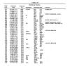
TMS0800 architecture and its program code example. While typing the program code from the badly blurred copies of the patent application was tedious and error prone work, took implementing the odd Sinclair Scientific based on the customer-specific TMC0805 a completely different approach:
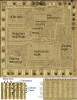
John McMaster de-capped and photographed an actual TMC0805 integrated circuit and the program code, operation masks, single-digit constants and the additional instructions of the instruction sets were visually retrieved from the enlarged die photos and implemented in the JavaScript Simulator, accordingly.
For an even better understanding of Texas Instruments' single-chip calculator circuits, the DCM-50A platform includes some means to peek inside the devices. When
Ken Shirriff developed the amazing
JavaScript Simulator for the
TMS0800, he relied on the United States
Patent Application
US3934233A describing the
TMS0800 architecture and its program code example. While typing the program code from the badly blurred copies of the patent application was tedious and error prone work, took implementing the odd Sinclair Scientific based on the customer-specific TMC0805 a completely different approach:
John McMaster de-capped and photographed an actual TMC0805 integrated circuit and the program code, operation masks, single-digit constants and the additional instructions of the instruction sets were visually retrieved from the enlarged die photos and implemented in the JavaScript Simulator, accordingly.
The US3934233A patent application describes in one chapter so-called test circuitry for the TMS0800, basically some shift registers to read out the 320 program words in a TI-specific test setup. Challenging is the timing of the clock and latch signals for these shift registers, the TMS0800 derives a four-phase clock from its internal clock oscillator and some additional external circuitry is necessary to reconstruct the four phases PHI-1 to PHI-4.
Kudos to Ken Shirriff and his team, comparing the electronically dumped program codes of the respective chips and the source codes used with the JavaScript Simulator reveals a perfect match. Okay, to be more precise: The program code from the patent application actually matches the TMS0801 used with the Canon LE-84 and not the TMS0803 used with the TI-1500 and TI-2500-II.
 In addition to the described features used to characterize single-chip calculator circuits, the DCM-50A platforms adds certain means to assist in reverse-engineering them:
| • Jumper for TMS0800 test mode • Two modes for TMS1000 test modes, externally controlled "digital reset" or externally controlled "analog reset", meaning switching the Reset-pin between VSS and an adjustable VRESET voltage • Externally provided clock signal for TMS0100, TMS0800, and TMS1000 devices • Recovery of internal clock signal from the Resistor-Capacitor oscillator for TMS0800 and TMS1000 • Digital Phase 1 recovery of internal or external TMS0800 clock from DK Signal • Analog Phase 1 recovery of internal or external TMS1000 clock from Reset Pin with adjustable current sensing amplifier • 2-bit Johnson ring counter to generate Clock Phases PHI-1 to PHI-4 for TMS0800 • 3-bit Johnson ring counter to generate Clock Phases PHI-1 to PHI-6 for TMS1000 and decoding internal clock signals PH1, PH2, and PH3 • Selector for Output-loads connected to VDD or GND • Levels-shifters (3.3V – 5.0V compatible) for all signals of Device-under-Test and various support signals Inputs: Clock, Test (Init), KN/KP/KO/KQ (K8/K4/K2/K1) Outputs: Clock, D1-D11 (R0-R10), SA-SH, SDP (O0-O7), PHI-1 to PHI-4 • 3.3V power supply with external voltage sensing for the level-shifters |
 All signals are made available on two connectors matching the pinout of the
Digilent
Digital Discovery™, a combined logic analyzer, protocol analyzer, and pattern generator instrument but can be used with any external instrument compatible with 3.3V or 5V signals.
All signals are made available on two connectors matching the pinout of the
Digilent
Digital Discovery™, a combined logic analyzer, protocol analyzer, and pattern generator instrument but can be used with any external instrument compatible with 3.3V or 5V signals.
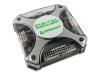
 Here at the Datamath Calculator Museum we are using both the Digilent Digital Discovery and
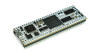
with the DCM-50A Sidekick a setup consisting of a
MicroNova
Mercury 2 Development Board based on the Artix-7 FPGA (Field-programmable Gate Array) interfacing with the DCM-50A
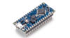
Platform and connected to an
Arduino Nano
Every for housekeeping.
Here at the Datamath Calculator Museum we are using both the Digilent Digital Discovery and
with the DCM-50A Sidekick a setup consisting of a
MicroNova
Mercury 2 Development Board based on the Artix-7 FPGA (Field-programmable Gate Array) interfacing with the DCM-50A
Platform and connected to an
Arduino Nano
Every for housekeeping.
Such a setup allows retrieving the 320 program words of a TMS0800 single-chip calculator circuit in less than 1 second – compared to hours for typing the program codes from a patent application or days for de-capping, photographing, and retrieving the bits from an actual chip.
If you have additions to the above article please email: joerg@datamath.org.
© Joerg Woerner, September 21, 2022. No reprints without written permission.