DATAMATH CALCULATOR MUSEUM
|
DATAMATH CALCULATOR MUSEUM |
Texas Instruments PC-100 Printer Cradle
| Date of introduction: | September 16, 1975 | Display technology: | |
| New price: | $295.00 (SRP 1976) | Display size: | |
| Size: | 10.4" x 11.3" x 4.1" | Printer technology: | Thermal TP-30250 |
| Weight: | 5 pounds 9 ounces | Serial No: | 013104 |
| Batteries: | Date of manufacture: | week 17 year 1976 | |
| AC-Adapter: | Origin of manufacture: | USA (LTA) | |
| Precision: | Integrated circuits: | TMC0251, TMC0561, TMC0569, 4*SN96912 | |
| Memories: | |||
| Program steps: | Courtesy of: | Joerg Woerner | |
| Download leaflet: | |
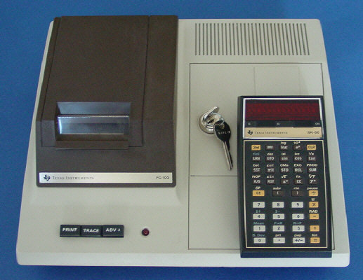 The
PC-100 Printer Cradle was introduced together with the
SR-52. Its thermal printer has 64 alphabetic, numeric and special characters which can be printed at the
rate of 60 characters per second. Up to 20 characters can be printed per line on
2.5 inch wide thermal paper.
The
PC-100 Printer Cradle was introduced together with the
SR-52. Its thermal printer has 64 alphabetic, numeric and special characters which can be printed at the
rate of 60 characters per second. Up to 20 characters can be printed per line on
2.5 inch wide thermal paper.
The PC-100 can also be used to print, list or trace program steps as an aid to debugging.
The PC-100 Printer Cradle in addition offers some extra features: It functions as a power-adapter and also has a storage/charging compartment where you can charge the battery pack. The calculator (and battery pack compartment) is locked solidly to the Printer Cradle with the use of a key.
 The
PC-100 sports a switch that makes it compatible with both the SR-52 and
SR-56.
The
PC-100 sports a switch that makes it compatible with both the SR-52 and
SR-56.
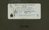 The featured PC-100 with Date code LTA 1776
was manufactured in April 1976 by Texas Instruments in their Lubbock, TX
facility. Dismantling the unit reveals a design centered around a mix of the
TMS0200 Building Blocks introduced in
1972 with the Canon Canola 121F and
the TMS0500 Building Blocks introduced in
January 1974 with the legendary SR-50 Scientific
calculator.
The featured PC-100 with Date code LTA 1776
was manufactured in April 1976 by Texas Instruments in their Lubbock, TX
facility. Dismantling the unit reveals a design centered around a mix of the
TMS0200 Building Blocks introduced in
1972 with the Canon Canola 121F and
the TMS0500 Building Blocks introduced in
January 1974 with the legendary SR-50 Scientific
calculator.
![]()
![]()
![]()
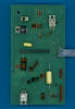
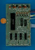 Main components of the electronics of the PC-100 are a
TMC0251 Printer/Display Chip that can
interface to both a Thermal Printer Mechanism or a Dot-Matrix Display and two
TMC0561 and
TMC0569 Bare Read-Only Memory (BROM) Chips
holding the firmware for the SR-52 respective SR-56 calculators. The previously
mentioned switch to select between the two calculators actually connects one of
the two "IRG" Pins of the BROMs to the
TMC0501E Enhanced Arithmetic Chip of the attached calculator.
Main components of the electronics of the PC-100 are a
TMC0251 Printer/Display Chip that can
interface to both a Thermal Printer Mechanism or a Dot-Matrix Display and two
TMC0561 and
TMC0569 Bare Read-Only Memory (BROM) Chips
holding the firmware for the SR-52 respective SR-56 calculators. The previously
mentioned switch to select between the two calculators actually connects one of
the two "IRG" Pins of the BROMs to the
TMC0501E Enhanced Arithmetic Chip of the attached calculator.
![]()
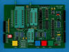
![]() The other
Integrated Circuits on the Main printed circuits board (PCB) are a TP4050AN Buffer
Chip for the two CLK signals of the TMC0501E architecture and four
SN96912N Driver Chips with six channels, each. Twenty of the channels are used for
the thermal print head and the remaining four channels are used for its stepper
motor.
The other
Integrated Circuits on the Main printed circuits board (PCB) are a TP4050AN Buffer
Chip for the two CLK signals of the TMC0501E architecture and four
SN96912N Driver Chips with six channels, each. Twenty of the channels are used for
the thermal print head and the remaining four channels are used for its stepper
motor.
 A
second PCB is wired with a flat ribbon cable to the Main PCB and with two
connectors to the docking connector and switches of the Printer Cradle. It
carries the electronics for the power supply of the PC-100 Printer Cradle and
three additional diodes for the key matrix inputs of the TMC0501E Chip.
A
second PCB is wired with a flat ribbon cable to the Main PCB and with two
connectors to the docking connector and switches of the Printer Cradle. It
carries the electronics for the power supply of the PC-100 Printer Cradle and
three additional diodes for the key matrix inputs of the TMC0501E Chip.
And last but not least holds a small third PCB the [PRINT],
[TRACE], [ADV] switches and the Power LED.
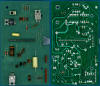
 Note: We removed the large heat sink of the TIP30 power
transistor (residual of the thermal paste still visible), the large power
transistor mounted upside down is a TIP120 when we prepared our
TMC0500 Platform to record the
ROM Image of the
TMC0561 and TMC0569 BROMs. Comparing the
Instruction ROM Content of the
TMC0561 used with the SR-52 and the TMC0569 used with the SR-56 shows as
expected many differences.
Note: We removed the large heat sink of the TIP30 power
transistor (residual of the thermal paste still visible), the large power
transistor mounted upside down is a TIP120 when we prepared our
TMC0500 Platform to record the
ROM Image of the
TMC0561 and TMC0569 BROMs. Comparing the
Instruction ROM Content of the
TMC0561 used with the SR-52 and the TMC0569 used with the SR-56 shows as
expected many differences.
The 12-pin docking connector uses 11 signals to communicate between the SR-52 or SR-56 calculator and the PC-100 Printer Cradle:
|
• Pin 1: KR (Key matrix input KR of TMC0501E) - Connected to BUSY output of TMC0251 • Pin 2: KP (Key matrix input KP of TMC0501E) - D0 PC-100 Present, D12 [PRINT] switch, D15 [TRACE] switch • Pin 3: KN (Key matrix input KN of TMC0501E) - D12 [ADV] switch • Pin 4: CLK 1 of TMC0500 Building Blocks • Pin 5: Digit Times Output D0 - PC-100 Present with KP • Pin 6: Digit Times Output D15 - [TRACE] switch KP • Pin 7: IRG (Instruction Words) of TMC0500 Building Blocks • Pin 8: IDLE (State and Digit Synchronization) of TMC0500 Building Blocks • Pin 9: EXT (External memory Access) of TMC0500 Building Blocks • Pin 10: CLK 1 of TMC0500 Building Blocks • Pin 11: Digit Times Output D12 - [ADV] switch KN and [PRINT] switch with KP • Pin 12: N/A (left most pin on printer cradle connector) |
The use of the Digit Times Output signal D0 to allow a connected calculator to detect presence or absence of the PC-100 is actually a show stopper for the SR-50A (Version 2) calculator, its revised electronics doesn't support scanning D0 like the SR-51A (Version 2) and the SR-56. Learn more about Printing with the SR-51 / SR-51A.
With the introduction of the TI-58 and
TI-59 the PC-100 was replaced with the PC-100A.
If you have additions to the above article please email: joerg@datamath.org.
© Joerg Woerner, September 25, 2002. No reprints without written permission.