DATAMATH CALCULATOR MUSEUM
|
DATAMATH CALCULATOR MUSEUM |
Texas Instruments introduced in 1973 with the TI-4000 Desktop calculator a very compact, yet capable product with a 12-digit display as an upgrade option to the TI-3000 and TI-3500 calculators with 8-digit resp. 10-digit displays. The TI-4000 was one of the first applications of TI’s TMS0200 Building Blocks for Desktop Calculators, a groundbreaking architecture centered around a Data Chip and various Support ICs:
|
• TMS0200 Data Chip – Register Processor with four 16-digit Registers and seven Keyboard Scan inputs • TMS0300 ROM Chip – 512*13 Bits Instruction Memory with serial interface to Data Chip and 13-digit display and keyboard scanning, up to 4 ROM Chips • TMC0400 ROM/Register Chip - 512*13 Bits Instruction Memory with parallel interface to ROM Chip and two 16-digit Registers • TMS0220 Printer Chip – Interface to two-color Drum Printer Mechanism • TMC0250 Printer/Display Chip – Interface to Thermal Printer Mechanism and Dot-Matrix Display |
The TMS0200 Data Chip requires in a minimum configuration – as used in the TI-4000 – a TMS0300 ROM Chip for Program Memory and to scan up to 13 digits of the display.
The TMS0220 Printer Chip allows for the addition of a two-color Drum Printer with up to 15 characters and 3 columns of function symbols to products based on the TMS0200 Building Blocks for Desktop Calculators.
Drum printers use a cylindrical drum with raised characters in bands for each printing position. The drum rotates at a rapid speed and for each possible print position there is a print hammer located behind the paper. These hammers strike the paper, along the ink ribbon, against the proper character on the drum as it passes. One revolution of the drum is required to print each line. Of the eighteen hammer driving outputs of the TMS0220 Printer Chip, fifteen are available for printing columns of data (decimal point, minus sign and numerals) and three are available for printing columns of function symbols. Typically, the print format is:
|
• 13 numerals, plus one floating minus sign, plus one decimal point, plus 3 symbols • When red ribbon is used, 14 numerals may be printed • The floating minus sign is printed to the left of the most significant nonzero digit (or decimal point) • The decimal point is printed in the central position of the character space • Each comma is a right-side print instead of a center-position print • Leading zeros are suppressed • For positive fractions and for negative fractions being printed in red, a zero is inserted to the left of the decimal point • If a minus sign is being used, then for negative fractions it is inserted to the left of the decimal point |
The TMS0221 is optimized for a Seiko Instruments, Inc. Model 104 drum printer mechanism operated at a motor speed of 2,400 rpm for printing at 300 lines per minute and uses the following signals to interface with its electronics:
|
• Fifteen Hammer Driver Outputs C1 – C15 for the 15 multi-symbol rings with 13 characters • Three Hammer Drivers Outputs for symbol rings F1 – F3 for function symbol rings • Thumper Output to strike selected Hammers • Pointer Output to indicate that a Digit has entered • Red Ribbon Output to indicate negative numbers • Paper Advance Output to advance paper and ribbon • Motor Drive Output to turn the drum motor on and off • TR Input indicating the Zero position of the printer drum • TP-TL Input for drum timing pulses |
The OPT A Input of the TMS0221 Printer Chip selects the mode of the drum motor:
|
• VSS Motor Drive continuous on • VDD Motor Drive controlled by software commands |
The interface between the TMS0200 Data Chip and TMS0220 Printer Chip uses two different communication methods:
|
• 16-digit BCD Data is transmitted digit by digit through the 4-bit I/O Bus I/O 8, I/O 4, I/O 2, and I/O 1 synchronized with both the FLAG and STROBE Inputs • 7-bit Function Data containing the row and column of the function symbol to be printed is transmitted serially through the EXT Input |
The BUSY Output of the TMS0221 Printer Chip connects with the corresponding input of the TMS0200 Data Chip to synchronize the components.
While none of the known products based on the TMS0200 Building Blocks makes fully use of their possibilities like addressing up to 4 ROM chips and up to 16 Register Chips, did the design lay out the architecture of the TMS0500 Building Blocks for Scientific Calculators introduced with the "Slide Rule" calculator SR-50 in January 1974 and leading all the way to the legendary TI Programmable 59 and the amazing SR-60A Prompting Desktop calculator.
With only a few designs based on the TMS0200 Building Blocks for Desktop Calculators using the optional TMS0220 Printer Chip and Texas Instruments numbering them in a sequential way, we can easily track the individual designs.
QUICK-LINK to TMS0200 Family.
Only certain Desktop and Scientific Calculators introduced between 1973 and 1974 by Texas Instruments, Canon, Olympia and Teal adopted the TMS0200 Architecture, while the TMC0250 Printer/Display Chip found its way into the wildly successful PC-100 Printer Cradle for the SR-51, SR-52, SR-56, TI-58, TI-58C, and TI-59 calculators and the SR-60 Prompting Calculator.
| Type | Calculators | Function |
| TMS0221 | TI-500, TI-620 | [+=] [-=] keys, 2 Memories, K Printer only. |
| Parameter | Min | Typ | Max | Unit | Comments |
| VSS | +9.2 | +10.0 | +10.6 | V | |
| VDD | 0 | V | |||
| VGG | -7.2 | -7.0 | -6.4 | V | |
| PHI1, PHI2 | 50 | 250 | 300 | kHz | Opposite phases |
The TMS0220 was manufactured in a metal gate PMOS process.
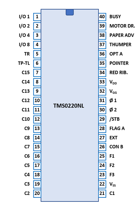
The TMS0200 uses a 0.6” wide 40-pin DIP (Dual In-line Package with a 0.1” / 2.54 mm lead pitch).
| Pin | IO | Function | Pin | IO | Function |
| 1 | IO | I/O Bus I/O 1 | 40 | O | Busy to TMS0200 |
| 2 | IO | I/O Bus I/O 2 | 39 | O | Motor on/off Control |
| 3 | IO | I/O Bus I/O 4 | 38 | O | Advance paper and ribbon |
| 4 | IO | I/O Bus I/O 4 | 37 | O | Key has entered |
| 5 | I | Drum Reset Pulse | 36 | I | Type of Drum Motor |
| 6 | I | Drum Timing Pulse Row | 35 | O | Digit has Entered |
| 7 | O | Hammer to Column 15 (left) | 34 | O | Negative Number |
| 8 | O | Hammer to Column 14 | 33 | V | VDD (0 V) |
| 9 | O | Hammer to Column 13 | 32 | V | VGG (-7 V) |
| 10 | O | Hammer to Column 12 | 31 | I | Input Clock 1 |
| 11 | O | Hammer to Column 11 | 30 | I | Input Clock 2 |
| 12 | O | Hammer to Column 10 | 29 | I | Digit Scan |
| 13 | O | Hammer to Column 9 | 28 | I | Flag A Data |
| 14 | O | Hammer to Column 8 | 27 | I | 7-bit Function Data |
| 15 | O | Hammer to Column 7 | 26 | I | Condition Flag B |
| 16 | O | Hammer to Column 6 | 25 | O | Hammer to Function (right) |
| 17 | O | Hammer to Column 5 | 24 | O | Hammer to Function |
| 18 | O | Hammer to Column 4 | 23 | O | Hammer to Function (left) |
| 19 | O | Hammer to Column 3 | 22 | V | VSS (+10 V) |
| 20 | O | Hammer to Column 2 | 21 | O | Hammer to Column 1 (right) |
If you have additions to the above datasheet please email: joerg@datamath.org.
© Joerg Woerner, March 11, 2021. No reprints
without written permission.