DATAMATH CALCULATOR MUSEUM
|
DATAMATH CALCULATOR MUSEUM |
 Back
in the days when the PC-100A Printer Cradle was introduced, there was a lot of
talk about its compatibility with the SR-51 and
SR-51A Scientific Calculators.
Although not officially supported by TI, several people were able to use the
PC-100A with
both
SR-51 and SR-51A by
putting the PC-100A in SR-52 mode. Some people found
that the print mode worked fine with their SR-51s but never could get the trace
mode to work, getting an "1" and a "?" on the printout. Here
at the Datamath Calculator Museum we developed in 2023 our
DCM-0500 (Platform) for
reverse-engineering of calculators based on the groundbreaking
TMS0500 Building Blocks and we decided
to finally solve the mystery about the epic question "Can I print with my SR-51
or SR-51A calculator?" The answer is pretty simple: "Kind of, but it depends..."
Back
in the days when the PC-100A Printer Cradle was introduced, there was a lot of
talk about its compatibility with the SR-51 and
SR-51A Scientific Calculators.
Although not officially supported by TI, several people were able to use the
PC-100A with
both
SR-51 and SR-51A by
putting the PC-100A in SR-52 mode. Some people found
that the print mode worked fine with their SR-51s but never could get the trace
mode to work, getting an "1" and a "?" on the printout. Here
at the Datamath Calculator Museum we developed in 2023 our
DCM-0500 (Platform) for
reverse-engineering of calculators based on the groundbreaking
TMS0500 Building Blocks and we decided
to finally solve the mystery about the epic question "Can I print with my SR-51
or SR-51A calculator?" The answer is pretty simple: "Kind of, but it depends..."
In a first step we need to look closer at the four different version of the PC-100 Printer Cradle:
|
• PC-100:
First design introduced with the SR-52, features [SR-56 - SR-52] switch
and TMC0561/TMC0569 BROM Chips • PC-100A: Second design introduced for the TI-58/TI-59, features [OTHER - SR-56 - SR-52] switch and TMC0561/TMC0569 BROM Chips • PC-100B: Third design, briefly available before PC-100C was released, [OTHER - SR-56 - SR-52] switch covered but still features TMC0561/TMC0569 BROM Chips • PC-100C: Final design, supports only TI-58, TI-58C and TI-59. Misses both [OTHER - SR-56 - SR-52] switch and TMC0561/TMC0569 BROM Chips |
Neither the SR-51 nor the SR-51A calculators are including the firmware for printing in their two SCOM (Scanning Read-Only Memory) Chips and rely instead on the TMC0561 BROM (Bare Read-Only Memory)Chip in the PC-100 Printer Cradle. Consequently are only the original PC-100 and the more common PC-100A Printer Cradles candidates for successful printing with the SR-51 and SR-51A. And yes, the TMC0561 holds the firmware extension for the SR-52 Programmable Calculator while the TMC0569 is responsible for the SR-56 Programmable Calculator.
In a second step we focus on the SR-51 and SR-51A Scientific Calculators:
|
• SR-51:
Original design of the SR-51 introduced in January 1975 and easily
recognized with its larger silver bezel below the display and covering
the top row of keys • SR-51A (Version 1): Cost-down version of the SR-51, much more common and easily recognized with its smaller silver bezel between the display and top row of keys • SR-51A (Version 2): Unified printed circuit board (PCB) design with both SR-50A and SR-56 but identical appearance. Products manufactured in the United States use a trailing B with the serial number |
The overview above lists only the three main types of SR-51 and SR-51A calculators, we observed during the life cycle of the calculators some minor differences that we will focus later on.
The mechanical and electrical interface with the SR-51/SR-51A calculators is accomplished by the key-actuated mounting bracket/connector on the PC-100/PC-100A Printer Cradles which fits into the battery pack opening in the calculator. For a successful printing with the SR-51/SR-51A both a mechanical fit and electrical compatibility is essential. Mounting the SR-51 on the PC-100/PC-100A Printer Cradle is finicky, we tested a few calculators and none fitted perfectly with the mounting brackets and battery contacts.
The 12-pin docking connector uses 11 signals to communicate between the SR-52 or SR-56 calculator and the PC-100 Printer Cradle:
|
• Pin 1: KR (Key matrix input KR of TMC0501E) - Connected to BUSY output of TMC0251 • Pin 2: KP (Key matrix input KP of TMC0501E) - D0 PC-100 Present, D12 [PRINT] switch, D15 [TRACE] switch • Pin 3: KN (Key matrix input KN of TMC0501E) - D12 [ADV] switch • Pin 4: CLK 1 of TMC0500 Building Blocks • Pin 5: Digit Times Output D0 - PC-100 Present with KP • Pin 6: Digit Times Output D15 - [TRACE] switch KP • Pin 7: IRG (Instruction Words) of TMC0500 Building Blocks • Pin 8: IDLE (State and Digit Synchronization) of TMC0500 Building Blocks • Pin 9: EXT (External memory Access) of TMC0500 Building Blocks • Pin 10: CLK 1 of TMC0500 Building Blocks • Pin 11: Digit Times Output D12 - [ADV] switch KN and [PRINT] switch with KP • Pin 12: N/A (left most pin on printer cradle connector) |
With major differences between the electronics of the three different main types of the SR-51 and SR-51A calculators we analyze each design individually.
 SR-51: Comparing
the Main-PCBs of four different evolutions of the SR-51
Scientific Calculator manufactured between August 1974 and May 1975, one month
before its discontinuation, shows only subtle differences in the layout but
holding a big surprise! The early three Main-PCBs have Pin 5 of the Print Cradle
connector floating while the SR-51 from the last production month has Pin 5
wired to Pin 14 of the TMC0522/TMC0523 SCOM
stack, its D0 Digit Time output. Looking into the
circuit diagrams of both the SR-52 Programmable Calculator and the PC-100 Print
Cradle we understand that a connection between D0 and the keymatrix input KP of
the TMC0501 Arithmetic Chip is used to detect the PC-100. Or in other words: Texas Instruments
consciously removed in the first iterations of the Main-PCB design the
capability of the SR-51 Firmware to detect a possibly connected PC-100 -
explaining why some SR-51 had success with printing and others not.
SR-51: Comparing
the Main-PCBs of four different evolutions of the SR-51
Scientific Calculator manufactured between August 1974 and May 1975, one month
before its discontinuation, shows only subtle differences in the layout but
holding a big surprise! The early three Main-PCBs have Pin 5 of the Print Cradle
connector floating while the SR-51 from the last production month has Pin 5
wired to Pin 14 of the TMC0522/TMC0523 SCOM
stack, its D0 Digit Time output. Looking into the
circuit diagrams of both the SR-52 Programmable Calculator and the PC-100 Print
Cradle we understand that a connection between D0 and the keymatrix input KP of
the TMC0501 Arithmetic Chip is used to detect the PC-100. Or in other words: Texas Instruments
consciously removed in the first iterations of the Main-PCB design the
capability of the SR-51 Firmware to detect a possibly connected PC-100 -
explaining why some SR-51 had success with printing and others not.
 To
avoid interference between sliding or locking switches and momentary push button
switches during keyboard scanning, the TMS0500 Building Blocks requires extra
diodes for all non-momentary switches. The SR-51 and SR-51A use a sliding [R-D]
switch for the selection of radians and degrees while the PC-100 Printer Cradle
uses a latching switch for the [TRACE] function. The additional hard-wired
connection to detect the presence of a PC-100 Printer Cradle act as an always-on
switch and consequently requires a diode inside the SR-51/SR-51A, too. The
keyboard mappings of the SR-51 and SR-51A are identical and use keymatrix inputs
KS for the [R-D] switch and KP for both the [TRACE] switch and presence
detection of the Printer Cradle PC-100, hence requiring two extra diodes.
To
avoid interference between sliding or locking switches and momentary push button
switches during keyboard scanning, the TMS0500 Building Blocks requires extra
diodes for all non-momentary switches. The SR-51 and SR-51A use a sliding [R-D]
switch for the selection of radians and degrees while the PC-100 Printer Cradle
uses a latching switch for the [TRACE] function. The additional hard-wired
connection to detect the presence of a PC-100 Printer Cradle act as an always-on
switch and consequently requires a diode inside the SR-51/SR-51A, too. The
keyboard mappings of the SR-51 and SR-51A are identical and use keymatrix inputs
KS for the [R-D] switch and KP for both the [TRACE] switch and presence
detection of the Printer Cradle PC-100, hence requiring two extra diodes.
The Diode D1 for keymatrix input KP is easy to
spot on the SR-51 PCB while the Diode D2 for keymatrix input KS is hiding in
plain sight - it is actually located on the larger display and keyboard PCB of
the calculator.
SR-51A (Version 1): During the analysis of the SR-51 we learned to focus
on three prerequisites for successful printing with a SR-51 or SR-51A Scientific
Calculator:
|
• Mechanical fit with the
key-actuated mounting bracket of the PC-100 Printer Cradle • Digit Time D0 output connected to Pin 5 of the PC-100 Printer Cradle connector • Two diodes wired on the SR-51 PCB for keymatrix inputs KS and KP |
The first bullet point is a no-brainer, the SR-51A is using the same housing as the SR-56 which was officially supported to work with the PC-100 and PC-100A Printer Cradle. Check.
 The connection between Pin 14 of the TMC0522/TMC0523 SCOM
stack (Digit Times output D0) and Pin 5 of the Printer Cradle connector is easily
visible on the PCB of the SR-51A (Version 1). Check.
The connection between Pin 14 of the TMC0522/TMC0523 SCOM
stack (Digit Times output D0) and Pin 5 of the Printer Cradle connector is easily
visible on the PCB of the SR-51A (Version 1). Check.
And
last but not least are two Diodes D1 and D2 mounted directly next to the
TMC0501E Enhanced Arithmetic Chip with traces running from the cathode of D1 to
Pin 9 (keymatrix input KS) and from the cathode of D2 to Pin 12 (keymatrix input
KP). Bingo
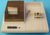
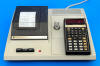
 We attached an SR-51A (Version 1) Scientific
Calculator on a PC-100A Printer Cradle, pushed the [TRACE] switch and started
entering some numbers, calculating the average and variance values and were
greeted with a crisp print-out. Quod erat demonstrandum.
We attached an SR-51A (Version 1) Scientific
Calculator on a PC-100A Printer Cradle, pushed the [TRACE] switch and started
entering some numbers, calculating the average and variance values and were
greeted with a crisp print-out. Quod erat demonstrandum.
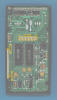
SR-51A (Version 2): With the SR-51A (Version 2) sharing its printed
circuit board (PCB) with the SR-56, we didn't expect any show-stopper for its
successful operating on a PC-100A Printer Cradle. And yes, the
SR-50A (Version 2) is using the same PCB, too but
disqualifies immediately for two reasons:
|
• PC-100 Printer Cradle
connector not gold-plated • TMC0531 SCOM Chip has Digit Time D0 output not bonded to its Pin 14 |
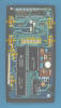
![]() We analyzed already the "Clock Generator Patch
Area" of the unified SR-50A/SR-51A (Version 2) and SR-56 PCB and learned that
the SR-51A uses like the SR-56 its second (TMC0533) SCOM Chip to generate the clock
signals and outputs the Digit Time D0 signal with its first (TMC0532) SCOM Chip. Comparing
the three PCB assemblies of the calculators reveals many differences and we are
not only concerned about the SR-51A missing the gold-plated PC-100 Printer
Cradle connector but seeing many more diodes on the SR-56 assembly than on the
SR-51A (Version 2) assembly.
We analyzed already the "Clock Generator Patch
Area" of the unified SR-50A/SR-51A (Version 2) and SR-56 PCB and learned that
the SR-51A uses like the SR-56 its second (TMC0533) SCOM Chip to generate the clock
signals and outputs the Digit Time D0 signal with its first (TMC0532) SCOM Chip. Comparing
the three PCB assemblies of the calculators reveals many differences and we are
not only concerned about the SR-51A missing the gold-plated PC-100 Printer
Cradle connector but seeing many more diodes on the SR-56 assembly than on the
SR-51A (Version 2) assembly.
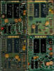
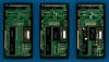
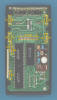
 Digging deeper into the visual differences, we
located a total of nine diodes on the SR-56 PCB but only four diodes on the
SR-51A (Version 2) PCB and started to reverse-engineer the schematics of the
calculators from the layout of the PCB and its populated components. The Diodes
D1 - D9 and Resistors R1, R2 are used for the functionality listed below:
Digging deeper into the visual differences, we
located a total of nine diodes on the SR-56 PCB but only four diodes on the
SR-51A (Version 2) PCB and started to reverse-engineer the schematics of the
calculators from the layout of the PCB and its populated components. The Diodes
D1 - D9 and Resistors R1, R2 are used for the functionality listed below:
|
• Diodes D1 (tip) and D2 (sleeve)
form the negative half of a full wave rectifier to charge the BP1A
Battery Pack • Diodes D3 (tip) and D4 (sleeve) form the positive half of a full wave rectifier to charge the BP1A Battery Pack • Diode D5 (with R1) and Diode D6 (with R2) limit the charging current of the batteries when the power switch of the calculator is in its [OFF] position • Diode D7 isolates the [R-D] switch together with Diode D8 from the keymatrix input KS • Diode D9 isolates the [TRACE] switch and presence detection of the Printer Cradle PC-100 from the keymatrix input KP |
 Matching the missing components of the SR-51A
(Version 2) PCB with the above listed overview of their respective purposes
results in the following list:
Matching the missing components of the SR-51A
(Version 2) PCB with the above listed overview of their respective purposes
results in the following list:
|
• The missing Diode D1 leaves
Diode D2 as a rectifier to charge the BP1A
Battery Pack • A piece of wire replacing Diode D3 and Diode D4 missing renders the full wave rectifier of the SR-56 to not even a half wave rectifier but single diode rectifier • Diode D5 (with R1) missing reduces the amount of charging current drop of the batteries when the power switch of the calculator is in its [OFF] position • Diode D7 and D8 are present, the [R-D] switch is isolated from the keymatrix input KS • Diode D9 replaced with a piece of wire connects the [TRACE] switch and presence detection of the Printer Cradle PC-100 with the keymatrix input KP. Ouch |
And consequently can't the SR-51A (Version 2) be used on the PC-100 Printer Cradle!
Including some minor variations observed during the life cycle of the SR-51 and SR-51A Scientific Calculators between 1975 and 1977 we created a "Compatibility Matrix" for successful printing with a PC-100 or PC-100A Printer Cradle:
| Calculator (Version) |
SCOM Chips |
Mechanical Fit? |
Gold-plated Connector? |
SCOM D0 Connected? |
KP Input Isolated? |
PC-100/PC100A Compatible |
|
SR-51 (First Design) |
TMC0522 TMC0523 |
NO | YES | NO | YES | NO |
|
SR-51 (Second Design) |
TMC0522 TMC0523 |
NO | YES | YES | YES | NO |
|
SR-51A (Version 1) |
TMC0522 TMC0523 |
YES | YES | YES | YES | YES |
|
SR-51A (Version 2) |
TMC0532 TMC0533 |
YES | NO | YES | NO | NO |
If you have additions to the above article please email: joerg@datamath.org.
© Joerg Woerner, February 24, 2024.
No reprints without written permission.