DATAMATH CALCULATOR MUSEUM
|
DATAMATH CALCULATOR MUSEUM |
With the TMS1802NC Texas Instruments announced on September 17, 1971 the first available standard calculator building block on a chip, it was later renamed into TMS0102. The chip integrates 3520-bit Read-Only program memory, a 182-bit Serial-Access memory and a decimal arithmetic logic unit as well as control, timing, and output decoders but no drivers for the display. This gives an overall complexity of roughly 5,000 transistors.
Gordon Moore, the co-founder of Fairchild Semiconductor and Intel predicted already in 1965 that the numbers of transistors in Large-scale Integration (LSI) chips would double every year for the next 10 years. In 1975, looking forward to the next decade, he revised the forecast to doubling every two years, a compound annual growth rate (CAGR) of 41%. While Moore did not use empirical evidence in forecasting that the historical trend would continue, his prediction held since 1975 and has since become known as a "law". Main enablers were and are a combination of both reducing the size of the individual components (process shrink) and increasing the chip size (yield improvement). The manufacturing costs of an Integrated Circuit (IC) are calculated with:
|
• IC cost = (Die cost + Testing cost + Packaging cost) / Final test yield |
 With the die cost roughly proportional to the die area, testing and packaging costs roughly proportional to the pin count, and the final test yield mostly inverse proportional to the die area, goals are well defined: Keep the die size as small as possible for a set of requirements agreed on. With both ROM (Read-Only Memory) and RWM (Read-Write Memory) sizes the main contributors to the die area
of a single-chip calculator circuit and shift-register based data memory (SAM,
Serial-Access Memory) of Register Processors denser than RAM (Random-Access Memory) of Digit Processors, Texas Instruments
expanded the TMS0100 Product Family two years after its introduction into three
different branches:
With the die cost roughly proportional to the die area, testing and packaging costs roughly proportional to the pin count, and the final test yield mostly inverse proportional to the die area, goals are well defined: Keep the die size as small as possible for a set of requirements agreed on. With both ROM (Read-Only Memory) and RWM (Read-Write Memory) sizes the main contributors to the die area
of a single-chip calculator circuit and shift-register based data memory (SAM,
Serial-Access Memory) of Register Processors denser than RAM (Random-Access Memory) of Digit Processors, Texas Instruments
expanded the TMS0100 Product Family two years after its introduction into three
different branches:
|
• TMS0600: Increased ROM (384 Words
* 11 Bits), Identical SAM (13 Digits Registers), external display drivers. Process shrink, higher functionality • TMS0700: Identical ROM (320 Words * 11 Bits), Identical SAM (13 Digits Registers), external display drivers. Process shrink, identical functionality, cost reduction of IC • TMS0800: Identical ROM (320 Words * 11 Bits), Reduced SAM (11 Digits Registers), integrated segment drivers. Process shrink, reduced functionality, higher integration |
Please notice that the members of the TMS0700 family were still marketed and marked as TMS0100 but both the die and the bottom of the chip package usually sport a TMS0700 marking.
 When
Texas Instruments introduced in Fall 1973 the TMS0800 Product Family, its focus was
clearly not on desktop calculators. Many features known from the TMS0100
Product Family, like support of 10-digit displays, fix-point selector switch,
selectable roundoff and
Adding Machine
Logic were removed from the specification sheet. Instead the TMS0800
addressed both manufacturing costs and user experience of battery operated
handheld calculators, integrating the previously external clock generator
and segment drivers, adding a low-battery indicator and extending the battery
life with an optional timeout feature. The algorithm of the chips were
improved, too; the TMS0803 for example features an Automatic Constant for
all four functions, integrates a percent function and even allows for
Decimal Alignment for addition and subtraction.
When
Texas Instruments introduced in Fall 1973 the TMS0800 Product Family, its focus was
clearly not on desktop calculators. Many features known from the TMS0100
Product Family, like support of 10-digit displays, fix-point selector switch,
selectable roundoff and
Adding Machine
Logic were removed from the specification sheet. Instead the TMS0800
addressed both manufacturing costs and user experience of battery operated
handheld calculators, integrating the previously external clock generator
and segment drivers, adding a low-battery indicator and extending the battery
life with an optional timeout feature. The algorithm of the chips were
improved, too; the TMS0803 for example features an Automatic Constant for
all four functions, integrates a percent function and even allows for
Decimal Alignment for addition and subtraction.
Comparing the TI-2500B introduced in January 1974 and still based on the TMS0119 with the TI-1500 introduced in April 1974 and based on the TMS0803, reveals a reduction of the component count and size of the bounding box by about 50% and we assume that manufacturing costs dropped with a similar percentage. Texas Instruments reused later the compact electronics of the TI-1500 in the boxy housing of the TI-2500-II and could consequently change the technology used for the printed circuit board dramatically to further reduce manufacturing costs.
We assume that less than ten designs were realized with the TMS0800 Product Family. As of today we know with the TMS0801, TMS0803 and TMS0807 three catalog products and two additional customer specific versions. The TMC0805 was designed together with Clive Sinclair and Nigel Searle for the incredible Sinclair Scientific, while the TMC0806 was designed with input from The Ohio State University for a Classroom Experiment that resulted in the development of the Exactra 19 calculator.
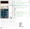
A typical calculator built around the TMS0800 series performs the four basic functions +, −, ×, and ÷ and might add the %- or √x-functions.
Texas Instruments introduced in Summer 1974 with the TMS0850 Product Family a variation of the TMS0800 with redesigned segment and digit output drivers, directly interfacing with low-voltage Vacuum Fluorescent Displays (VFDs) up to 35 Volts. The last step in the evolution of the TMS0800 could be found with the TMS0830 Product Family introduced in Winter 1974, technically identical with the TMS0800 but specified for 9 Volts battery operation.
Manufacturers of battery operated 5-function handheld calculators could select in 1975 between more than a dozen American, European and Japanese calculator chip suppliers, namely AMI, Cal-Tex, Commodore/MOS Technology, Electronic Arrays, General Instrument, Hitachi, Litronix, Matsushita, Mitsubishi, Mostek, National Semiconductor, NEC, Omron, RFT, Rockwell, Sharp, Texas Instruments, Toshiba, and Western Digital. While Texas Instruments owned in 1972/1973 the market of single-chip calculator circuits with the famous TMS0100 series, offered in 1975 many of these companies more functionality than the TMS0800 design could offer with its limited Instruction ROM with only 320 Words * 11 Bits capacity. Texas Instruments consequently replaced the TMS0800 early in 1975 with the TMS0950 and the TMS0850 in 1976 with the TMS1040, both offering an enlarged Instruction ROM of 1,024 Words * 8 Bits capacity.
| Type | Calculators | Keyboard | Constant (M-D-A-S) |
Digits | Fixed DP | Timeout | Rounding | Special Functions |
Seg./Dig. Blanking |
(6,7,9) Font |
Seg. H Low V. |
Entry Overflow |
Calculating Overflow |
| TMS0801 | Bowmar MX-20, Canon LE-84, Craig 4511, Kovac LE-808, Sinclair Cambridge | [+][−][=] | 2-2-2-2 | 8 | Float | Yes | None | S1, S11 S1, S11 |
FLASHING DISPLAY |
||||
| TMS0803 | TI-1500, TI-2500-II, Exactra 21, Exactra 22, Exactra 23, Kovac LE-808O, Montgomery Ward P100, Western Auto M4993 | [+][−][=] | 1-2-2-2 | 8 | Float (A-S) Auto |
Yes | None | [%] | S1, S11 S1, S11 |
||||
| TMC0805 | Sinclair Scientific | [+][−][E] | 5+2 | Fix EE | No | None | [sin][cos][tan] [sin-1][cos-1][tan-1] [log][ex] |
S1, S11 S1, S11 |
|||||
| TMC0806 | Exactra 19 | [+][−][=] | 1-2-2-2 | 6 | Float (A-S) Auto |
Yes | None | [%] | NONE NONE |
||||
| TMS0807 | Canon Palmtronic LE-85, Commodore 885D, Kovac 808R, Prinztronic Mini 7 | [+][−][=] | 1-2-2-2 | 8 | Float | Yes | None | [%±][√x][RE] | S1, S11 S1, S11 |
| Description | Comments | |
| Architecture | Single-chip Calculator | Second Generation |
| Category | Register Processor | BCD-serial |
| Related |
TMS0830 TMS0850 |
9 Volts Operation, LED 35 Volts VFD Outputs |
| ROM Size | 3,520 Bits | 320 Words * 11 Bits |
| RAM Size | 154 Bits | 3 Registers * 11 Digits, 2 * 11 Bit-Flags |
| Outputs | 9 Digits 8/9 Segments |
External Digit Drivers Internal Segment Drivers |
| Inputs | 3 Keyboard 0/1 Low Voltage Detection |
Digit to Keyboard Scan-Matrix |
Capacity: Up to 8 digits (positive and negative)
Logic: Algebraic Chain Logic with Automatic Constant
[2] [x] [3] [+] [4] [x] [5] [=] → '50.'
Number Entry: Right-justified number entry, entering a ninth digit is ignored
[1] [2] [3] [4] [5] [6] [7] [8] [9] → '12345678.'
Decimal Point: First entered decimal point is used, additional decimal point entries are ignored
[1] [.] [2] [.] [3] → '1.23'
Fixed Decimal Point: Fixed decimal point arithmetic is not supported
Decimal Alignment: Decimal alignment is not supported for additions and subtractions
[0] [.] [4] [5] [+] [0] [.] [5] [5] [=] → '1.'
Clear: Automatic power-up clear implemented. [C] key clears the whole calculator, [CE] key clears last entry of a number
[1] [+] [2] [C] [3] [=] → '3.'; [1] [+] [2] [CE] [3] [=] → '4.'
Change Sign: Not supported. When performing multiplication or division, a negative value is assigned to a number by pressing the [−] key before entering the number
[−] [2] [x] [3] [=] → '-6.'; [−] [2] [x] [−] [3] [=] → '6.'
Number Display: Right-justified number display with leading-zero suppression
Negative Numbers: Negative numbers are shown with '-' floating immediate left of the number
Calculating Overflow: An overflow shows the result flashing with the decimal point shifted 8 positions to the left and is only recoverable using the [C] key
[1] [2] [3] [4] [5] [x] [1] [2] [3] [4] [5] [=] → '*1.5239902*'
Divide By Zero: A division of a positive or negative number by zero shows a flashing '0' and is only recoverable using the [C] key
[1] [:] [0] [=] → '*0.*'; [−] [1] [:] [0] [=] → '*0.*'
Timeout: If selected, the display blanks out about 20 seconds after the last operation and shows only a '-' in the leftmost digit. Timeout is recoverable with an optional [D] key or interrupted with the [=] or [C] keys
[1] [2] .. 20 seconds → '-', [D] [3] → '123.'
Rounding: Rounding of displayed calculating results is not supported
[2] [0] [:] [3] [=] → '6.6666666'
Automatic Constant: Implemented for multiplication (2nd number used as constant), division (2nd), addition (2nd), and subtraction (2nd)
[3] [x] [2] [=] [=] → '12.', [1] [=] → '2.'; [4] [x] [=] [=] → '64.'
[3] [:] [2] [=] [=] → '0.75', [1] [=] → '0.5.'; [4] [:] [=] [=] → '0.25'
[3] [+] [2] [=] [=] → '7.', [1] [=] → '3.'; [4] [+] [=] [=] → '12.'
[3] [−] [2] [=] [=] → '-1.', [1] [=] → '-1.'; [4] [−] [=] [=] → '-4.'
Known Calculator Logic Bugs: NoneCapacity: Up to 8 digits (positive and negative)
Logic: Algebraic Chain Logic with Automatic Constant
[2] [x] [3] [+] [4] [x] [5] [=] → '50.'
Number Entry: Right-justified number entry, entering a ninth digit is ignored
[1] [2] [3] [4] [5] [6] [7] [8] [9] → '12345678.'
Decimal Point: First entered decimal point is used, additional decimal point entries are ignored
[1] [.] [2] [.] [3] → '1.23'
Fixed Decimal Point: Fixed decimal point arithmetic is not supported
Decimal Alignment: Decimal alignment is supported for additions and subtractions
[0] [.] [4] [5] [+] [0] [.] [5] [5] [=] → '1.00'
Clear: Automatic power-up clear implemented. [C] key clears the whole calculator, [CE] key clears last entry of a number
[1] [+] [2] [C] [3] [=] → '3.'; [1] [+] [2] [CE] [3] [=] → '4.'
Change Sign: Not supported. When performing multiplication or division, a negative value is assigned to a number by pressing the [−] key before entering the number
[−] [2] [x] [3] [=] → '-6.'; [−] [2] [x] [−] [3] [=] → '6.'
Number Display: Right-justified number display with leading-zero suppression
Negative Numbers: Negative numbers are shown with '-' floating immediate left of the number
Calculating Overflow: An overflow shows the result with the decimal point shifted 8 positions to the left and 'C' (or 'E' for negative numbers) in the leftmost position. It is recoverable using the [C] or [CE] keys
[1] [2] [3] [4] [5] [x] [1] [2] [3] [4] [5] [=] → 'C1.5239902'
Divide By Zero: A division of a positive or negative number by zero shows a '0' and 'C' in the leftmost position. It is recoverable using the [C] or [CE] keys
[1] [:] [0] [=] → 'C 0.'; [−] [1] [:] [0] [=] → 'C 0.'
Timeout: If selected, the display blanks out about 20 seconds after the last operation and shows only a '-' in the leftmost digit. Timeout is recoverable with an optional [D] key or interrupted with the [=], [C] or [CE] keys
[1] [2] .. 20 seconds → '-', [D] [3] → '123.'
Rounding: Rounding of displayed calculating results is not supported
[2] [0] [:] [3] [=] → '6.6666666'
Automatic Constant: Implemented for multiplication (1st number used as constant), division (2nd), addition (2nd), and subtraction (2nd)
[3] [x] [2] [=] [=] → '18.', [1] [=] → '3.'; [4] [x] [=] [=] → '64.'
[3] [:] [2] [=] [=] → '0.75', [1] [=] → '0.5.'; [4] [:] [=] [=] → '0.25'
[3] [+] [2] [=] [=] → '7.', [1] [=] → '3.'; [4] [+] [=] [=] → '12.'
[3] [−] [2] [=] [=] → '-1.', [1] [=] → '-1.'; [4] [−] [=] [=] → '-4.'
Percent Function: The [%] key is implemented for addition, subtraction, multiplication, and division. Using the [=] key following the [%] key in multiplication or division leads to unexpected result
[2] [0] [+] [5] [%] → '1.', [=] → '21.'
[2] [0] [−] [5] [%] → '-1.', [=] → '19.'
[2] [0] [x] [5] [%] → '1.', [=] → '21.'
[5] [:] [2] [0] [%] → '25.', [=] → '1.25'
Known Calculator Logic Bugs:
Residual Trailing Zero Bug: Certain calculations result in displaying trailing zeros
[1] [:] [1] [0] [0] [0] [0] [=] → '0.0001', [=] → '0.', [+] [1] [=] → '1.0000'
Capacity: Up to 5 digits (positive and negative) for mantissa and up 2 digits (positive and negative) for exponent
Logic: Polish Notation with fixed decimal point scientific notation
[2] [+] [3] [x] [4] [+] [5] [x] → '5.0000 E01'
Number Entry: Left-justified number entry, entering a fifth digit for the mantissa is ignored. The exponent uses the last two entered numbers
[1] [2] [3] [4] [5] [6] → '1.2345 E00'; [1] [E] [2] [3] [4] → '1.0000 E34'
Decimal Point: The virtual decimal point is placed after the first digit of the mantissa
[1] [.] [2] [.] [3] → '1.2300 E00'
Fixed Decimal Point: All arithmetic is performed with a fixed virtual decimal point
Decimal Alignment: Not supported
[0] [4] [5] [+] [0] [5] [5] [+] → '1.0000 E00'
Clear: Automatic power-up clear implemented. [C] key clears the whole calculator
[1] [+] [2] [C] [3] [+] → '3.0000 E00'
Change Sign: Not supported. When entering an exponent, a negative value is assigned to a number by pressing the [−] key before entering the number
[1] [E] [−] [2] [=] → '1.0000 E-02'; [1] [−] E] [−] [2] [=] → '-1.0000 E-01'
Number Display: Left-justified number display beginning with digit D5 for mantissa and digit D7 for exponent. Fixed virtual decimal point between Digits D5 and D4
Negative Numbers: Negative numbers are shown with '-' at leftmost position D9. Negative exponents are output at D8
Calculating Overflow: Calculating overflow or underflow is not detected
[1] [2] [E] [5] [5] [+] [1] [2] [E] [5] [5] [x] → '1.4400 E10'; [1] [2] [E] [−] [5] [5] [+] [1] [2] [E] [−] [5] [5] [x] → '1.4400 E-10'
Divide By Zero: A division of a positive or negative number by zero is not detected
[1] [+] [0] [:] → '0.0000 E00'; [1] [−] [0] [:] → '0.0000 E00'
Timeout: Not supported
Rounding: Rounding of displayed calculating results is not supported
Automatic Constant: Not supported. If a function is used without entering a new number, the function will multiply, divide, add, or subtract the previous number from itself
[4] [+] [x] → '1.6000 E01'
[4] [+] [:] → '1.0000 E00'
[4] [+] [+] → '8.0000 E00.'
[4] [−] [−] → '0.0000 E00.'
Transcendental and Trigonometric Functions: The eight transcendental and trigonometric functions are used in post-fixed mode and operate on the number entered before or the number in the display
Capacity: Up to 6 digits (positive and negative)
Logic: Algebraic Chain Logic with Automatic Constant
[2] [x] [3] [+] [4] [x] [5] [=] → '50.'
Number Entry: Right-justified number entry, entering a seventh digit is ignored
[1] [2] [3] [4] [5] [6] [7] → '123456.'
Decimal Point: First entered decimal point is used, additional decimal point entries are ignored
[1] [.] [2] [.] [3] → '1.23'
Fixed Decimal Point: Fixed decimal point arithmetic is not supported
Decimal Alignment: Decimal alignment is supported for additions and subtractions
[0] [.] [4] [5] [+] [0] [.] [5] [5] [=] → '1.00'
Clear: Automatic power-up clear implemented. [C] key clears the whole calculator, [CE] key clears last entry of a number
[1] [+] [2] [C] [3] [=] → '3.'; [1] [+] [2] [CE] [3] [=] → '4.'
Change Sign: Not supported. When performing multiplication or division, a negative value is assigned to a number by pressing the [−] key before entering the number
[−] [2] [x] [3] [=] → '-6.'; [−] [2] [x] [−] [3] [=] → '6.'
Number Display: Right-justified number display beginning with digit D3 and leading-zero suppression. Not used digits D1 and D2 output '00'
Negative Numbers: Negative numbers are shown with '-' floating immediate left of the number
Calculating Overflow: An overflow shows the 6 most significant digits of the result together with five decimal points and 'C' (or 'E' for negative numbers) in the leftmost position. It is recoverable using the [C] or [CE] keys
[1] [2] [3] [4] [5] [x] [1] [2] [3] [4] [5] [=] → 'C1.5.23.9.9.'
Divide By Zero: A division of a positive or negative number by zero shows six '0' together with five decimal points and 'C' in the leftmost position. It is recoverable using the [C] or [CE] keys
[1] [:] [0] [=] → 'C0.0.0.0.0.0'; [−] [1] [:] [0] [=] → 'C0.0.0.0.0.0'
Timeout: If selected, the display blanks out about 20 seconds after the last operation and shows only a '-' in the leftmost digit. Timeout is recoverable with an optional [D] key or interrupted with the [=], [C] or [CE] keys
[1] [2] .. 20 seconds → '-', [D] [3] → '123.'
Rounding: Rounding of displayed calculating results is not supported
[2] [0] [:] [3] [=] → '6.66666'
Automatic Constant: Implemented for multiplication (1st number used as constant), division (2nd), addition (2nd), and subtraction (2nd)
[3] [x] [2] [=] [=] → '18.', [1] [=] → '3.'; [4] [x] [=] [=] → '64.'
[3] [:] [2] [=] [=] → '0.75', [1] [=] → '0.5.'; [4] [:] [=] [=] → '0.25'
[3] [+] [2] [=] [=] → '7.', [1] [=] → '3.'; [4] [+] [=] [=] → '12.'
[3] [−] [2] [=] [=] → '-1.', [1] [=] → '-1.'; [4] [−] [=] [=] → '-4.'
Percent Function: The [%] key is implemented for addition, subtraction, multiplication, and division. Using the [=] key following the [%] key in multiplication or division leads to unexpected result
[2] [0] [+] [5] [%] → '1.', [=] → '21.'
[2] [0] [−] [5] [%] → '-1.', [=] → '19.'
[2] [0] [x] [5] [%] → '1.', [=] → '21.'
[5] [:] [2] [0] [%] → '25.', [=] → '1.25'
Known Calculator Logic Bugs: NoneCapacity: Up to 8 digits (positive and negative)
Logic: Algebraic Chain Logic with Automatic Constant
[2] [x] [3] [+] [4] [x] [5] [=] → '50.'
Number Entry: Right-justified number entry, entering a ninth digit is ignored
[1] [2] [3] [4] [5] [6] [7] [8] [9] → '12345678.'
Decimal Point: First entered decimal point is used, additional decimal point entries are ignored
[1] [.] [2] [.] [3] → '1.23'
Fixed Decimal Point: Fixed decimal point arithmetic is not supported
Decimal Alignment: Decimal alignment is not supported
[0] [.] [4] [5] [+] [0] [.] [5] [5] [=] → '1.'
Clear: Automatic power-up clear implemented. [C] key clears the whole calculator, [CE] key clears last entry of a number
[1] [+] [2] [C] [3] [=] → '3.'; [1] [+] [2] [CE] [3] [=] → '4.'
Change Sign: Not supported. When performing multiplication or division, a negative value is assigned to a number by pressing the [−] key before entering the number
[−] [2] [x] [3] [=] → '-6.'; [−] [2] [x] [−] [3] [=] → '6.'
Number Display: Right-justified number display with leading-zero suppression
Negative Numbers: Negative numbers are shown with '-' in the left most position
Calculating Overflow: An overflow shows the result with the decimal point shifted 8 positions to the left and 'u' (or 'o for negative numbers) in the leftmost position. It is recoverable using the [C] or [CE] keys
[1] [2] [3] [4] [5] [x] [1] [2] [3] [4] [5] [=] → 'u1.5239902'
Divide By Zero: A division of a positive or negative number by zero shows a '0' and 'u' or 'o' respectively in the leftmost position. It is recoverable using the [C] or [CE] keys
[1] [:] [0] [=] → 'u 0.'; [−] [1] [:] [0] [=] → 'o 0.'
Timeout: If selected, the display blanks out about 20 seconds after the last operation and shows only a '-' in the leftmost digit. Timeout is recoverable with an optional [D] key or interrupted with the [=], [C] or [CE] keys
[1] [2] .. 20 seconds → '-', [D] [3] → '123.'
Rounding: Rounding of displayed calculating results is not supported
[2] [0] [:] [3] [=] → '6.6666666'
Automatic Constant: Implemented for multiplication (1st number used as constant), division (2nd), addition (2nd), and subtraction (2nd)
[3] [x] [2] [=] [=] → '18.', [1] [=] → '3.'; [4] [x] [=] [=] → '64.'
[3] [:] [2] [=] [=] → '0.75', [1] [=] → '0.5.'; [4] [:] [=] [=] → '0.25'
[3] [+] [2] [=] [=] → '7.', [1] [=] → '3.'; [4] [+] [=] [=] → '12.'
[3] [−] [2] [=] [=] → '-1.', [1] [=] → '-1.'; [4] [−] [=] [=] → '-4.'
Percent Function: The [%±] is implemented for addition and subtraction for add-on and discount calculations
[2] [0] [x] [5] [%±] → '1.', [+] [=] → '21.'
[2] [0] [x] [5] [%±] → '1.', [−] [=] → '19.'
Register Exchange: The [RE] key allows the exchange of the display register with the operand register before completing the calculation
[2] [:] [3] → '3.', [RE] → '1,5.', [=] → '0.75.'
Known Calculator Logic Bugs:
Negative Square Root Bug: Negative square roots are allowed and result in a negative number
[8] [√x] → '2.8284271'; [−] [8] [√x] → '-2.8284271'
Zero Square Root Bug: Calculating the square root immediately after a previous calculation that resulted in a zero is generating an erroneous display
[1] [−] [1] [=] → '0.', [√x] → '0.0000000'
Square Root Chain Bug: The result of a square root calculation can't be used as an operand in a chain calculation w/o pressing the [=] key before the function key
[4] [√x] → '2.', [+] [1] [=] → '1.'
[4] [√x] → '2.', [=] → '2.', [+] [1] [=] → '3.'
| Device | Top Markings Bottom Markings |
Calculator Serial Number |
Instruction ROM ©Texas Instruments |
| TMS0801NC | TMS0801NCΔ 7421 J0801 22 |
Canon LE-84 859570 |
|
| TMS0803NC | TMS0803NC 7421-1 J0803P |
TI-2500-II 055 058376 |
|
| TMC0805NC | TMC0805NC 7418 0805P |
Sinclair Scientific 0033437 |
|
| TMC0806NC | TMC0806NC A7441 D0806AP |
Exactra 19 444 1900039332 |
|
| TMS0807NC | TMS0807NCΔ 7431 J0807 31 |
Canon LE-85 508295 |
IMPORTANT NOTE: This information is provided as a service of the Datamath Calculator Museum to enthusiasts of early Texas Instruments calculators and please be aware that the Copyright of the Software transcribed in the ROM Images, the underlying algorithm or application might be owned by Texas Instruments or other third parties. The commercial use of the published Recorded ROM Images is strictly prohibited. In case of questions please contact us using the email address listed in the footer of this webpage.
| Item | Min | Typ | Max | Unit | Comments |
| VSS | 0 | V | |||
| VDD | -16.3 | -10.0 | -9.5 | V | |
| VGG | -16.3 | -15.8 | -15.3 | V | |
| IDD | 2.0 | mA | REXT = 100 kOhm, Segment- and | ||
| IGG | 1.0 | mA | Digit-Driver Load 100 kOhm to VDD | ||
| Int. CK | 100 | 160 | 200 | kHz | REXT = 100 kOhm to VDD |
| Ext. CK | 100 | 160 | 200 | kHz | REXT = 0 Ohm to VSS |
CLOCK GENERATOR
All devices of the TMS0800 Product Family include an internal clock oscillator that can be enabled by pulling Pin 14 (REXT/Clock Select) with a resistor REXT to VDD. The internal clock frequency is then output on Pin 13 (OSC Out/Clock Input) for test purposes. Connecting Pin 14 directly to VSS disables the internal clock oscillator and the chip can be operated through an external clock signal with frequencies between 100 kHz and 200 kHz applied to Pin 13. The external clock frequency should have a duty cycle close to 50% and oscillate between VSS and VDD.
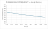
The frequency of the internal clock oscillator is set with the external resistor REXT, its nominal value is 100 kOhm for a typical frequency of 160 kHz. We observed values between 100 kOhm and 180 kOhm used on the printed circuit boards (PCBs) of various calculator based on TMS0800 devices. Here at the Datamath Calculator Museum we operate the TMS0800 Devices-under-Test (DUT) with an external 100 kOhm resistor but verify its operation between 50 kOhm and 150 kOhm.
The operating frequency of the internal clock oscillator depends not only on the external resistor, but its supply voltages VDD and VGG, too. We observed with our DUT opposite gradients of the oscillation frequency for VDD and VGG variations.
LOW VOLTAGE DETECTION
The chip design of the TMS0800 single-chip calculator circuit allows to configure Pin 5 (SH/LV) either as Segment Driver Output H (used for the Fancy Four) or as Low Voltage Input to display a warning symbol like 'L' on the leftmost position of a 9-digit LED (Light-Emitting-Diode) Display. All known designs of the TMS0800 use Pin 5 configured as Low Voltage Input but only few designs make actually use of it. Having Pin 5 floating open or tied to VSS will disable outputting the warning symbol on Digit D9, pulling it down to VDD enables the warning output. We observed with our DUT a threshold of about -2.7 V and measured the internal pull-up resistor with about 25k Ohm at VLV = -2.0 V.
TIMEOUT FEATURE
To increase the operating time of battery-powered handheld calculators, Texas Instruments designed for the TMS0800 Product Family a so-called Timeout feature. When no key presses are detected for about 20 seconds, the display blanks out and shows only a '-' in the leftmost digit to reduce power consumption of the calculator. Timeout is recoverable with an optional [D] key connected between the WDK Output and either the KN or KO Inputs, or pressing any key assigned to the keyboard scan matrix D8, D9/KN, KO, KP.
All designs of the TMS0800 Product Family but the TMC0805 have the [C] and [=] keys assigned to the D8 and/or D9 keyboard scan outputs, allowing to recover Timeout with these two keys. Many calculators do not make use of the Timeout feature and simply connect Pin 10 (WDK) and Pin 8 (KN) with a short trace on the printed circuit board (PCB).
The Datamath Calculator Museum DCM-50A (Platform) supports the TMS0800 Product Family with its center TMS0800 Textool Test Socket set to DCM-50A (TMS0800) mode. Both Characterization of TMS0800 Calculator Circuits and Reverse-engineering of TMS0800 Calculator Circuits is supported by the DCM-50A (TMS0800).
The DCM-50A Sidekick TMS0800 ROM Recorder attached to the DCM-50A (TMS0800) allows Recording of all TMS0800 Product Family Members including the TMS0830 and TMS0850 Devices.
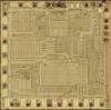
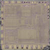
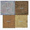
The TMS0800 was manufactured in a 8 um metal gate PMOS process (metal width = 0.30 mil / 8.0 um, metal spacing = 0.35 mil / 9.0 um, diffusion width = 0.25 mil / 6.0 um, diffusion spacing = 0.30 mil / 8.0 um).
The die size of the TMS0800 is approximately 200 mils * 195 mils / 5.0 mm * 5.0 mm.
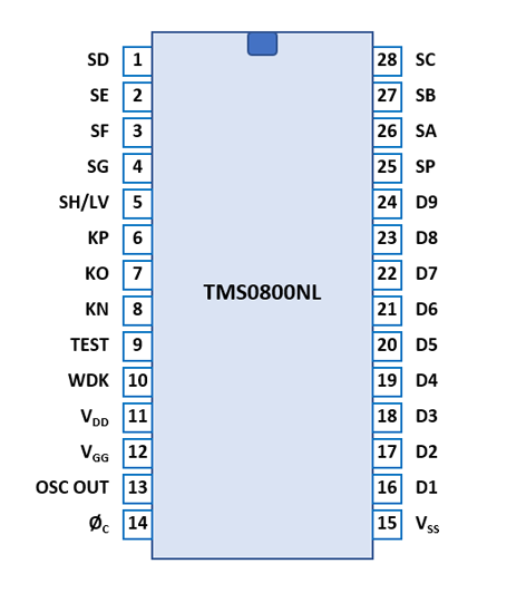
The TMS0800 uses a standard 0.6” wide 28-pin DIP (Dual In-line Package with a 0.1” / 2.54 mm lead pitch).
| Pin | IO | Function | Pin | IO | Function |
| 1 | O | Segment driver D | 28 | O | Segment driver C |
| 2 | O | Segment driver E | 27 | O | Segment driver B |
| 3 | O | Segment driver F | 26 | O | Segment driver A |
| 4 | O | Segment driver G | 25 | O | Segment driver DP |
| 5 | IO | Seg. H/Low Voltage | 24 | O | Digit driver 9 (sign) |
| 6 | I | Key-matrix input P | 23 | O | Digit driver 8 (MSD) |
| 7 | I | Key-matrix input O | 22 | O | Digit driver 7 |
| 8 | I | Key-matrix input N | 21 | O | Digit driver 6 |
| 9 | I | Test (VSS) | 20 | O | Digit driver 5 |
| 10 | O | Digit scan DK | 19 | O | Digit driver 4 |
| 11 | V | Negative Voltage VDD | 18 | O | Digit driver 3 |
| 12 | V | Negative Voltage VGG | 17 | O | Digit driver 2 |
| 13 | IO | OSC Out/Clock Input | 16 | O | Digit driver 1 (LSD) |
| 14 | I | REXT/Clock Select | 15 | V | Common Voltage VSS |
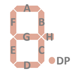
| The Segment drivers A-G and DP (Decimal Point) are
connected to the display in the pictured way. The optional SH/LV signal can be configured as Segment H or Low Voltage indicator. |
 |
The keyboards of all calculators based on the TMS0800 Product Family consist of an x/y-matrix connected to nine digit-driver outputs and the key-matrix inputs KN (Numbers), KO (Operations) and KP (Additional Operations).
The TMS0800 integrates a timer to shut off the display after a certain amount of time with the calculator not in use, the reset of the timer can be accomplished either with an extra [D] key connected between the digit scan DK signal and the key-matrix input KO line or simply by shorting DK output with the KN input.
Scanning is performed in D9 → D1 direction at a rate of about 370 Hz:
|
• State Time = 4 Clocks = 0.025 ms @ CK=160 kHz • Digit Time = 11 States (1 Instruction Cycle) = 0.275 ms @ CK=160 kHz • Scan Time = 10 Digit Times (D1 to D10 with D10 a dead cycle) = 2.75 ms @ CK=160 kHz |
TMS0801 |
TMS0803 |
||||||
| KN | KO | KP | KN | KO | KP | ||
| D1 | 9 | 0 | D1 | 9 | 0 | ||
| D2 | 8 | . | D2 | 8 | . | ||
| D3 | 7 | CE | D3 | 7 | % | ||
| D4 | 6 | ÷ | D4 | 6 | ÷ | ||
| D5 | 5 | × | D5 | 5 | × | ||
| D6 | 4 | − | D6 | 4 | − | ||
| D7 | 3 | + | D7 | 3 | + | ||
| D8 | 2 | = | D8 | 2 | = | CE | |
| D9 | 1 | C | D9 | 1 | C | ||
| DK | -TR- | (D) | DK | -TR- | (D) | ||
TMC0805 |
TMS0806 |
||||||
| KN | KO | KP | KN | KO | KP | ||
| D1 | 9 | 0 | D1 | 9 | 0 | ||
| D2 | 8 | E | D2 | 8 | . | ||
| D3 | 7 | ▲ | D3 | 7 | % | ||
| D4 | 6 | × | D4 | 6 | ÷ | ||
| D5 | 5 | ÷ | D5 | 5 | x | ||
| D6 | 4 | − | D6 | 4 | − | ||
| D7 | 3 | + | D7 | 3 | + | ||
| D8 | 2 | ▼ | D8 | 2 | = | CE | |
| D9 | 1 | C | D9 | 1 | C | ||
| DK | DK | -TR- | (D) | ||||
TMS0807 | |||
| KN | KO | KP | |
| D1 | 9 | 0 | |
| D2 | 8 | . | |
| D3 | 7 | ÷ | |
| D4 | 6 | × | |
| D5 | 5 | − | |
| D6 | 4 | + | |
| D7 | 3 | = | % |
| D8 | 2 | CE | √x |
| D9 | 1 | C | RE |
| DK | -TR- | (D) | |
Calculators based on the TMS0800 typically make use of 9-digit LED (Light-Emitting-Diode) Displays with common cathode architecture. Some designs with 9-digit low-voltage VFDs (Vacuum Fluorescent Displays) are known.
Learn more about the TMS0800 with Ken Shirriff's animated JavaScript Simulator for the TMS0800:
|
•
TMS0803 Simulator:
TI-2500-II (w/o [%]-key) • TMC0805 Simulator: Sinclair Scientific |
If you have additions to the above datasheet please email: joerg@datamath.org.
© Joerg Woerner, February 02, 2001. No reprints
without written permission.