DATAMATH CALCULATOR MUSEUM
|
DATAMATH CALCULATOR MUSEUM |
Texas Instruments announced on September 17, 1971 with the TMS1802NC the first available standard calculator building block on a chip, it was later renamed into TMS0102. The chip integrates 3,520 Bits Read-Only program Memory (ROM, 320 Words * 11 Bits), a 182-bit Serial-Access Memory (SAM, 3 Registers * 13 Digits, 2 * 13 Bit-Flags) and a decimal arithmetic logic unit as well as control, timing, and output decoders but no drivers for the display.
The TMS1802NC single-chip calculator circuit was later renamed to TMS0102 and Texas Instruments sold millions and millions of TMS0100 chips to calculator manufacturers like Bowmar, Canon, Hearthkit, and Toshiba and dozens more while using them in their own calculators like TI-2500, TI-3000, and TI-3500, too.
While the U.S. Patent Office ruled that Texas Instruments engineer Gary W. Boone is the inventor of the single-chip microcontroller, didn’t gain the TMS0100 any traction outside of the calculator business. Although the Register Processor architecture of the TMS0100 proved to be very efficient on operands stored in its three shift registers based 13-digit Registers, were digit manipulations rather inefficient and needed to cycle a complete 13-digit word through the ALU while masking twelve of the thirteen digits. Consequently, Texas Instruments introduced in October 1974 with the TMS1000 their first Digit Processor by replacing the 182-bit Serial-Access Memory with a 256-bit Random-Access Memory organized as 64 Digits or the equivalent of 4*16-digit Registers and changing the width of the instructions from 11-bit to 8-bit. The new architecture allowed to access any 4-bit data memory location with the means of a pointer gaining a lot of flexibility in digit manipulations bit losing performance on register operations typically used in electronic calculators.
Despite the fact that TI’s first application of the TMS1001 was the SR-16 scientific calculator, took the TMS1000 family off in other applications from appliances to garage door openers to toys and within a few years annual sales volume was in the tens of millions.
The original TMS1000 chip introduced in October 1974 had similar characteristics as the TMS0100, but later members of the growing product portfolio increased memory capacity, number of output latches, and output driver characteristics:
| Chip Series | TMS0100 | TMS1000 | TMS1200 | TMS1070 | TMS1270 | TMS1100 | TMS1300 | TMS1170 | TMS1370 | TMS1400 | TMS1600 | TMS1470 | TMS1670 | TMS1700 |
| Technology | PMOS | PMOS | PMOS | PMOS | PMOS | PMOS | PMOS | PMOS | PMOS | PMOS | PMOS | PMOS | PMOS | PMOS |
| Supply Voltage | 7.2V, 14.4V | 15V or 9V | 15V or 9V | 15V or 9V | 15V or 9V | 15V or 9V | 15V or 9V | 15V or 9V | 15V or 9V | 15V or 9V | 15V or 9V | 15V or 9V | 15V or 9V | 15V or 9V |
| Pins, Package | 28 DIP | 28 DIP | 40 DIP | 28 DIP | 40 DIP | 28 DIP | 40 DIP | 28 DIP | 40 DIP | 28 DIP | 40 DIP | 28 DIP | 40 DIP | 28 DIP |
| Instruction ROM (Words, Bits) |
320*13 3,520 |
1k*8 8,192 |
1k*8 8,192 |
1k*8 8,192 |
1k*8 8,192 |
2k*8 16,384 |
2k*8 16,384 |
2k*8 16,384 |
2k*8 16,384 |
4k*8 32,768 |
4k*8 32,768 |
4k*8 32,768 |
4k*8 32,768 |
512*8 4,096 |
| Data Storage (Files, Digits, Bits) |
3*13 SAM 156+26 |
4*16 RAM 256 |
4*16 RAM 256 |
4*16 RAM 256 |
4*16 RAM 256 |
8*16 RAM 512 |
8*16 RAM 512 |
8*16 RAM 512 |
8*16 RAM 512 |
8*16 RAM 512 |
8*16 RAM 512 |
8*16 RAM 512 |
8*16 RAM 512 |
2*16 RAM 128 |
| K Input Lines (Keyboard Scan) |
4 | 4 | 4 | 4 | 4 | 4 | 4 | 4 | 4 | 4 | 8 | 4 | 8 | 4 |
| R Output Latches (Digits Scan) |
11 | 11 | 13 | 11 | 13 | 11 | 16 | 11 | 16 | 11 | 16 | 10 | 16 | 9 |
| O Outputs (Segments) |
9 (11 on Die) |
8 | 8 | 8 | 10 | 8 | 8 | 8 | 8 | 8 | 8 | 8 | 8 | 8 |
| Output PLA (Inputs, Outputs Terms) |
5
to 11 18 |
5
to 8 20 |
5
to 8 20 |
5
to 8 20 |
5
to 10 20 |
5
to 8 20 |
5
to 8 20 |
5
to 8 20 |
5
to 8 20 |
5
to 8 20 |
5
to 8 20 |
5
to 8 20 |
5
to 8 20 |
5
to 8 20 |
| Output Drivers (Display Technology) |
None | None LED Level |
None LED Level |
VFD | VFD | None LED Level |
None LED Level |
VFD | VFD | None LED Level |
None LED Level |
VFD | VFD |
None LED Level |
While the TMS1000 Microcomputer Product Family was wildly successful in non-calculator applications and made its most prominent appearance in the Speak & Spell toy, was the original design used only with three TI calculators.
| Type | Calculator | Application | Comments |
| TMS1001 | SR-16 | Scientific | First TMS1000 application |
| TMS1014 | TI-5050 | Printing | With TMS1214 |
| TMS1016 | SR-16 II, Zayre Concept III | Scientific | Successor of SR-16 |
| TMS1000/CD8000 | PC-800 | Printer | With TMS1300/CD8020 |
| Description | Comments | |
| Architecture | Single-chip Calculator | First Generation Digit Processor |
| Category | Digit Processor | 4-bit Digits |
| Related |
TMS1000 Portfolio TMS0950 TMS1040 |
Different # of Inputs and Outputs, different Output drivers |
| ROM Size | 8,192 Bits | 1,024 Words * 8 Bits |
| RAM Size | 256 Bits | 4 Registers * 16 Digits |
| Outputs | 11 Digits 8 Segments |
External Digit Drivers Internal segment Drivers |
| Inputs | 4 Keyboard 0 Miscellaneous |
Digit to Keyboard Scan-Matrix |
The Datamath Calculator Museum DCM-50A (Platform) supports TMS1000 chips directly with the TMS1000 Textool Test Socket set to DCM-50A (TMS1000) mode. Both Characterization of TMS1000 Calculator Circuits and Reverse-engineering of TMS1000 Calculator Circuits is supported by the DCM-50A (TMS1000).
| Parameter | Min | Typ | Max | Unit | Comments |
| VSS | 0 | V | |||
| VDD | -14 | -15 | -17.5 | V | 15V Series |
| VDD | -7.5 | -9 | -10 | V | 9V Series |
| IDD | 4.5 | 10 | mA | 300 kHz, -15V | |
| VOUT | 0.3 | VDD | V | Output Voltage | |
| Ext. CK | 100 | 400 | kHz | Level between VSS and VDD | |
| Int. CK | 250 | 300 | 350 | kHz | Rext= 50 kOhm, Cext= 47 pF |
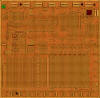
The original TMS1000 was manufactured in a 8 um metal gate PMOS process (metal width = 0.30 mil / 8.0 um, metal spacing = 0.35 mil / 9.0 um, diffusion width = 0.25 mil / 6.0 um, diffusion spacing = 0.35 mil / 9.0 um).
The die size of the TMS1000 is approximately 200 mils * 200 mils / 5.1 mm * 5.1 mm.
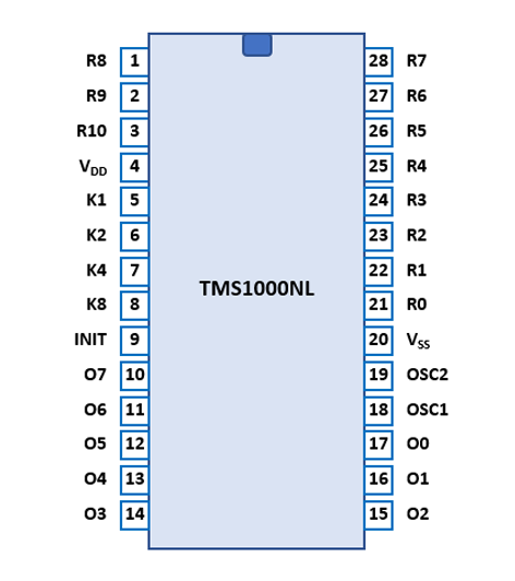
The TMS1000 is using in TI's calculator applications a standard 0.6” wide 28-pin DIP (Dual In-line Package with a 0.1” / 2.54 mm lead pitch).
| Pin | IO | Function | Pin | IO | Function |
| 1 | O | R8 Output | 28 | O | R7 Output |
| 2 | O | R9 Output | 27 | O | R6 Output |
| 3 | O | R10 Output | 26 | O | R5 Output |
| 4 | V | Negative Voltage VDD | 25 | O | R4 Output |
| 5 | I | K1 Input | 24 | O | R3 Output |
| 6 | I | K2 Input | 23 | O | R2 Output |
| 7 | I | K4 Input | 22 | O | R1 Output |
| 8 | I | K8 Input | 21 | O | R0 Output |
| 9 | I | INIT (Reset) | 20 | V | Common Voltage VSS |
| 10 | O | O7 Output | 19 | I | OSC2 (Ext. CLK = VSS) |
| 11 | O | O6 Output | 18 | I | OSC1 (Cext, Rext) or Ext |
| 12 | O | O5 Output | 17 | O | O0 Output |
| 13 | O | O4 Output | 16 | O | O1 Output |
| 14 | O | O3 Output | 15 | O | O2 Output |
In a typical calculator application the digits of the display are connected with drivers to the
scanning R Outputs, the segments of the display are connected directly or with drivers to the O Outputs making use of the
provided 5 to 8 PLA to decode the segments, and the keyboard matrix is connected
between the K Inputs and R Outputs.
Example for the SR-16 II:
| Pin | IO | Function | Pin | IO | Function |
| 1 | O | Digit driver 10 | 28 | O | Digit driver 9 |
| 2 | O | Digit driver 11 (M-LSD) | 27 | O | Digit driver 8 |
| 3 | O | Digit driver 3, 12 (OVER) | 26 | O | Digit driver 7 |
| 4 | V | Negative Voltage VDD | 25 | O | Digit driver 6 |
| 5 | I | K1 Input | 24 | O | Digit driver 5 |
| 6 | I | K2 Input | 23 | O | Digit driver 4 (M-LSD) |
| 7 | I | K4 Input | 22 | O | Digit driver 2 (E-MSD) |
| 8 | I | K8 Input | 21 | O | Digit driver 1 (E-LSD) |
| 9 | I | INIT (Reset) | 20 | V | Common Voltage VSS |
| 10 | O | Segment driver DP | 19 | I | OSC2 (Connected to OSC1) |
| 11 | O | Segment driver G | 18 | I | OSC1 (100 pF, 30 kOhm) |
| 12 | O | Segment driver F | 17 | O | Segment driver A |
| 13 | O | Segment driver E | 16 | O | Segment driver B |
| 14 | O | Segment driver D | 15 | O | Segment driver C |
| The Segment drivers A-G and DP (Decimal Point) are connected to the display in the pictured way. | 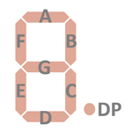 |
The keyboards of calculators based on the TMS1000 Product Family consist of an x/y-matrix connected to the R Outputs R0-R10 and the K Inputs K1, K2, K4, and K8 allowing for a maximum of 44 switches.
Example for the SR-16 II with TMS1016:
| K1 | K2 | K4 | K8 | |
| R0 - D1 | C | |||
| R1 - D2 | CD | 0 | ||
| R2 - D4 | 1 | |||
| R3 - D5 | +/− | 2 | ||
| R4 - D6 | x2 | 3 | ||
| R5 - D7 | log | EE | 4 | |
| R6 - D8 | √x | + | . | 5 |
| R7 - D9 | lnx | − | STO | 6 |
| R8 - D10 | 1/x | × | RCL | 7 |
| R9 - D11 | eX | ÷ | SUM | 8 |
| R10 - D3,12 | yX | = | PI | 9 |
Calculators based on the TMS1000 use all kinds of displays. Texas Instruments recommended for LED (Light-Emitting-Diode) Displays the corresponding segment drivers SN75491 and digit drivers SN75492.
If you have additions to the above datasheet please email: joerg@datamath.org.
© Sean Riddle and Joerg Woerner, January 17, 2021. No reprints
without written permission.