DATAMATH CALCULATOR MUSEUM
|
DATAMATH CALCULATOR MUSEUM |
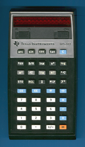
Texas Instruments SR-50 (Version 1)
| Date of introduction: | January 15, 1974 | Display technology: | LED modules + lens |
| New price: | $169.95, DM 520.00 | Display size: | 10 + 2 |
| Size: | 5.8" x 3.2" x
1.3" 147 x 81 x 32 mm3 |
||
| Weight: | 8.5 ounces, 240 grams | Serial No: | 0033437 |
| Batteries: | BP1 | Date of manufacture: | wk 21 year 1974 |
| AC-Adapter: | AC9200 | Origin of manufacture: | USA |
| Precision: | 13 | Integrated circuits: | TMC0501, TMC0521, 2*SN27882 |
| Logic: | Sum-of-Products | Displays: | 14*DIS279 |
| Memories: | 1 | ||
| Program steps: | Courtesy of: | Joerg Woerner | |
| Download leaflets: |
|
Download manual: | |
![]()
![]()
 This
wonderful SR-50 marked a milestone in the history of
calculators manufactured by Texas Instruments. It added trigonometric and
hyperbolic functions, the logarithms and their inverses to the scientific
functions of the SR-10 and SR-11. The "Slide Rule" calculator SR-50 was pit
with big success against Hewlett-Packard's HP-35 and
sold in high quantities.
The internal construction was very rigid compared with other models and on par
with the well respected HP-35.
This
wonderful SR-50 marked a milestone in the history of
calculators manufactured by Texas Instruments. It added trigonometric and
hyperbolic functions, the logarithms and their inverses to the scientific
functions of the SR-10 and SR-11. The "Slide Rule" calculator SR-50 was pit
with big success against Hewlett-Packard's HP-35 and
sold in high quantities.
The internal construction was very rigid compared with other models and on par
with the well respected HP-35.

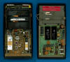
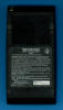 Dismantling the featured SR-50 Scientific calculator with
Date code 214 and manufactured in May 1974 in
Dallas, Texas reveals a perfectly engineered design based on a sandwich of two
printed circuit boards (PCBs) separated with a plastic frame holding the
electric contacts for the rechargeable BP1
Battery Pack using three AA-sized NiCd cells and mounting hardware for the PCBs
and the bottom shell of the housing.
Dismantling the featured SR-50 Scientific calculator with
Date code 214 and manufactured in May 1974 in
Dallas, Texas reveals a perfectly engineered design based on a sandwich of two
printed circuit boards (PCBs) separated with a plastic frame holding the
electric contacts for the rechargeable BP1
Battery Pack using three AA-sized NiCd cells and mounting hardware for the PCBs
and the bottom shell of the housing.
![]()
![]()
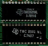
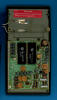 The smaller of the two PCBs is centered
around the "Calculator Brain" composed of the two
TMC0501 Arithmetic and
TMC0521 Scanning and Read-Only Memory Chips and
supported by power supply and clock signal generation realized with multiple
discrete components. With the BP1 battery pack having a nominal voltage of
around 3.7 Volts but the calculator chips manufactured in a 8 um metal gate PMOS
process requiring two voltages of -10.0 Volts and -15.8 Volts, does the SR-50
include a transformer based DC/DC converter designed with discrete components.
The two calculator chips use two non-overlapping clock signals PHI 1 and PHI 2
with a frequency of up to 250 kHz, to optimize the power budget of the SR-50 an
innovative clock circuitry slows down the clock frequency of the system while
the calculator is just displaying results and scanning the keyboard and not
performing actual calculations.
The smaller of the two PCBs is centered
around the "Calculator Brain" composed of the two
TMC0501 Arithmetic and
TMC0521 Scanning and Read-Only Memory Chips and
supported by power supply and clock signal generation realized with multiple
discrete components. With the BP1 battery pack having a nominal voltage of
around 3.7 Volts but the calculator chips manufactured in a 8 um metal gate PMOS
process requiring two voltages of -10.0 Volts and -15.8 Volts, does the SR-50
include a transformer based DC/DC converter designed with discrete components.
The two calculator chips use two non-overlapping clock signals PHI 1 and PHI 2
with a frequency of up to 250 kHz, to optimize the power budget of the SR-50 an
innovative clock circuitry slows down the clock frequency of the system while
the calculator is just displaying results and scanning the keyboard and not
performing actual calculations.
![]()
![]()
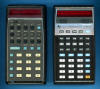
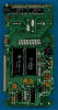
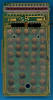 The larger of the two PCBs contains the display of the
calculator composed of 14 discrete 7-Segment LED modules with an attached
magnifier lens and two SN27882 display drivers but most of the real estate is dedicated
to the 40 snap action switches of the keyboard. Tracing back to the reliable Klixon™ switches and using double shot injection molding keys,
the SR-50 might be TI's most reliable calculator ever produced. Time will tell.
The larger of the two PCBs contains the display of the
calculator composed of 14 discrete 7-Segment LED modules with an attached
magnifier lens and two SN27882 display drivers but most of the real estate is dedicated
to the 40 snap action switches of the keyboard. Tracing back to the reliable Klixon™ switches and using double shot injection molding keys,
the SR-50 might be TI's most reliable calculator ever produced. Time will tell.
When Hewlett-Packard formally introduced on January 4th, 1972 its
revolutionary HP-35, it seemed to be far ahead of the four bangers like Bowmar's
Model 901B based on Texas
Instruments' "calculator-on-a-chip"
technology introduced just 3 months earlier with the
TMS1802, later rebranded as TMS0102. And
Hewlett-Packard indeed designed the HP-35 based on a multi-chip architecture
using five separate chips, each with a complexity of around 5,000 transistors
comparable to the TMS1802 and manufactured by either Mostek Corp., Carrollton, TX or American Microsystems Inc., Santa Clara, CA.
Texas Instruments was no stranger to multi-chip architectures, more or less in
parallel with the TMS1802 they worked for Canon on the TMC1813/TMC1814 chipset
for their Canola L121F Desktop
calculator leading directly into the
TMS0200 Building Blocks for Desktop
calculators. They are centered around the TMS0200
Data Chip, TMS0300 ROM (Read-Only Memory)
Chip and TMC0400 ROM/Register Chip. But
each of the three Chips was encapsulated in a large 40-pin Dual In-line Package
(DIP) making them unsuitable for a handheld product.
Being already late, Texas Instruments knew that they needed to be better than their competition and they analyzed the hot-selling HP-35 carefully to identify some weaknesses of its design:
|
• RPN (Reverse Polish Notation)
is very efficiently implemented in a scientific calculator, but for the average user it might be prohibitive • While the HP-35 was the first portable electronic calculator featuring transcendental functions, does it lack hyperbolic functions • Using a bit-serial architecture, the algorithm used to implement the transcendental functions were a tradeoff of accuracy and speed • And last but not least the US$ 395 price tag |
Various teams at Texas Instruments were addressing each of these bullet points and this SR-50 was their answer! When the calculator was formally introduced in January 1974, Hewlett-Packard immediately lowered the sales price of the HP-35 from US$ 395 to US$ 295!
Based on the architecture of the TMS0200 Building Blocks a team under Michael J. Cochran designed the TMS0500 Building Blocks for Scientific and Programmable Calculators first used with the SR-50. Following Moore's law, the observation that the number of transistors in an integrated circuit (IC) doubles about every two years, TI made major improvements to the individual Building Blocks from TMS0200 to TMS0500:
| TMS0200/TMS0500 Building Block |
16-bit Registers | Instruction Memory | Constant Memory | Display Scanning | Segment Decoder | Keyboard Scanning |
| TMS0200 Data Chip |
4 | External | 7 Inputs | |||
| TMC0501 Arithmetic Chip |
5 | Internal with Drivers | 7 Inputs | |||
| TMS0300 ROM Chip |
512*13 Bits max. 1 Chip |
13 Outputs | ||||
| TMC0400 ROM/Register Chip |
2 | 512*13 Bits max. 3 Chips |
||||
| TMC0520 SCOM Chip |
2 | 1,024*13 Bits max. 8 Chips |
16*16 Digits | 16 Outputs |
The SR-50 utilized only the bare minimum of the capabilities of the TMS0500 Building Blocks for Scientific and Programmable Calculators but the subsequent introduction of the SR-52 Programmable and the PC-100 Printer Cradle clearly demonstrated the scalability of this groundbreaking architecture. While from a technology point of view the SR-60A Prompting Calculator marked the eclipse of the TMS0500 Building Blocks, was it the TI Programmable 59 that will be remembered for eternity. And the TI-58C lastly will be remembered for combining a Continuous Memory in modern CMOS technology with the PMOS technology of the TMC0501 tracing back to the Sixties before Project X converted the successor of the TI-59 into a pure CMOS design known as TI Programmable 88.
And yes, the SR-50 proudly features an orange [=] key to differentiate it from the blue, double-wide [ENTER] key of the HP-35 and sparked many discussions about the most appropriate Logic for Scientific calculators. It the early days of electronic calculators, transistor count mattered and Registers used to store interims calculating results consume a lot of transistors competing on the silicon real estate of calculator chips with the Instruction Memory defining the functionality of the calculator.
In mathematics the order of
operations are defined rules for the order of evaluating mathematical
expressions to avoid any ambiguity while allowing notations being as brief as
possible.
The simple key sequence [2] [x] [3] + [4] [x] [5] used with an
electronic calculator could lead to different results without establishing these
rules. Modern algebraic notation follows the PEMDAS approach, meaning the
following hierarchy is used in the evaluation of expressions:
|
• 1) Parentheses • 2) Exponentiation • 3) Multiplication and Division • 4) Addition and Subtraction |
The acronym PEMDAS is mainly used in the
United States to memorize with the mnemonic phrase "Please Excuse My Dear Aunt Sally" the order of operations,
Speakers of British English often use BODMAS, replacing parentheses with
brackets and Exponents with Orders, while Canadian English speakers split the
difference with BEDMAS. Anyway, parentheses are the tool to redefine the
evaluation of mixed expressions like the example above:
(2 x 3) + (4 x 5) =
26
2 x (3 + 4) x 5 = 70
2 x [3 + (4 x 5)] = 46 etc.
With early electronic calculators mainly competing with adding
machines, the first calculator chip designs supported "Adding
Machine Logic" that requires just three Registers, one each for Entry,
Display/Result, and Second Operand/Interims Result. TI's first Single-Chip
Calculator Circuit implemented four Registers, allowing "Enhanced
Adding Machine Logic" with an additional Accumulation Memory or "Enhanced
Chain Logic" with supporting either an additional Constant or a User Memory. The SR-50 design based
on the TMC0501 Arithmetic Chip and one TMC0521 Scanning Read-Only Memory (SCOM)
Chip features a combined seven Registers like the HP-35 but TI decided to
implement "Sum-of-Products Logic" that was as efficient as Reverse Polish Notation Logic but very close
to the PEMDAS approach. Without offering keys for parentheses, it allowed
entering the (2 x 3) + (4 x 5) expression as key sequence [2] [x] [3] + [4] [x]
[5] [=] and yielding the correct answer of 26 with 8 keystrokes, while RPN
requires 9 keystrokes: [2] [ENTER] [3] [x] [4] [ENTER] [5] [x] [+]. The not so
common (2 + 3) x (4 + 5) expression on the other hand would require the key
sequence [2] [+] [3] [=] [STO] [4] [+] [5] [=] [x] [RCL] [=] or 12 keystrokes,
while RPN still requires 9 keystrokes.
One major improvement of the TMS0500 Architecture was dedicated space for constants, frequently used with computing algorithm of trigonometric functions like sine, cosine, or tangent and number conversions like millimeters to inches. With typical serial architectures used in electronic calculators, one instruction would load just one digit of a number and consequently for numbers represented in Scientific calculators with 12 to 15 digits, the algorithm would tend to be rather slow. Texas Instruments introduced with the TMS0500 Building Blocks a novel approach to load constants containing 16 digits within one Digit Time or instruction cycle from the Constant Memory to the TMC0501 Arithmetic Chip.
The SR-50 - and all subsequent designs based on the TMC0520 SCOM Chip - stores 16 constants with 13-digit precision in the Constant ROM:
| Constant Address |
16-digit SCOM Content (I/O 8 - 1, MSB first) |
Value c of Expression (≥ 13 digits) |
Expression |
| 00 | 230258509299400C | 2.302585092994 | c = ln (10) |
| 01 | 0693147180559945 | 0.69314718055995 | c = ln (2) |
| 02 | 0095310179804325 | 0.095310179804325 | c = ln (1.1) |
| 03 | 0009950330853168 | 0.0099503308531681 | c = ln (1.01) |
| 04 | 0000999500333084 | 0.00099950033308342 | c = ln (1.001) |
| 05 | 0000099995000333 | 0.000099995000333297 | c = ln (1.0001) |
| 06 | 0000009999950000 | 0.0000099999500003988 | c = ln (1.00001) |
| 07 | 0000000999999500 | 0.00000099999949991807 | c = ln (1.000001) |
| 08 | 0785398163397450 | 0.78539816339745 | c = arctan (1) |
| 09 | 0099668652491200 | 0.099668652491162 | c = arctan (0.1) |
| 0A | 0009999666686670 | 0.0099996666866652 | c = arctan (0.01) |
| 0B | 0000999999666667 | 0.00099999966666687 | c = arctan (0.001) |
| 0C | 0000099999999667 | 0.000099999999666667 | c = arctan (0.0001) |
| 0D | 157079632679501C | 1.57079632679486 | c = pi ÷ 2 |
| 0E | 314159265359000C | 3.141592653589793238 | c = pi |
| 0F | 572957795130801C | 5.729577951308 | c = 18 ÷ pi |
Compared to the HP-35 Architecture, the SR-50 was superior in many aspects:
While Hewlett-Packard had to juggle the tradeoffs between accuracy and speed of the algorithm used to implement the transcendental functions of the HP-35 with its bit-serial architecture, could TI's team utilize both a digit-serial architecture and the dedicated space for constants. Consequently scored the SR-50 in the precision of the internal algorithm very well and outperformed competitors for years to come.
A handy tool to demonstrate the accuracy of the implemented algorithm of transcendental functions is Mike Sebastian's "Calculator Forensics" test and comparing the result of the expression arcsin(arccos(arctan(tan(cos(sin (9)))))) with the expected result of 9 (with the calculator in degrees mode):
| Calculator | Introduction | Chip Set Instruction ROM Size |
Result |
| Hewlett-Packard HP-35 (w/ ROM bug) |
January 1972 | MK6020, MK6021 768*10 bits |
9.002983113 |
| Hewlett-Packard HP-35 |
January 1973 | MK6020, MK6021 768*10 bits |
9.004076901 |
| Texas Instruments SR-50 |
January 1974 | TMC0501, TMC0520-2,3 1,024*13 bits |
9.000005272880 |
| Texas Instruments SR-50 (Version 2) |
July 1974 | TMC0501, TMC0520-4,5 1,024*13 bits |
9.000004661314 |
The tradeoff between accuracy and speed of computing algorithm actually has with cost a third parameter:
|
• Speed: With transcendental function not
expressible as a finite combination of the algebraic operations, approximations
are used. Higher accuracy translates to longer execution time of the
algorithm • Accuracy: Higher accuracy of the transcendental functions requires more significant digits for the numbers used in the approximation algorithm • Cost: Higher speed requires faster number crunching resulting in more complex CPU architectures and high accuracy increased register sizes, both resulting in larger and hence more expensive chips |
Hewlett-Packard settled for the Arithmetic and Register Circuit used in the HP-35 with a bit-serial architecture representing numbers in 56 bits, divided into 4 bits for the sign of the mantissa, 40 bits for the mantissa, 4 bits for the sign of the exponent, and 8 bits for the exponent. Texas Instruments picked for the Arithmetic Chip used with the SR-50 a digit-serial architecture representing numbers in 16*4 bits, divided into one digit (4 bits) for the signs of both mantissa and exponent, 13 digits for the mantissa and 2 digits for the exponent. As mentioned a major advantage, adding two 10-digit accurate numbers in HP's architecture takes 56 clock cycles, TI's architecture on the other hand could add two 13-digit accurate numbers in 16 clock cycles. TI obviously a clear winner, but let's look into the related costs. The manufacturing costs of an Integrated Circuit (IC) are calculated with:
|
• IC cost = (Die cost + Testing cost + Packaging cost) / Final test yield |
With the die cost roughly proportional to the die area, testing and packaging costs roughly proportional to the pin count, and the final test yield mostly inverse proportional to the die area, goals are well defined: Keep the die size as small as possible for a set of requirements agreed on..
Die sized of the chips used with the HP-35 are well documented in Fred Beckhusen's wonderful article about the HP-35 Bluebird Tester:
| Chip | Function | Die Size | Package |
| MK6020 | Arithmetic and Register Circuit | 156 mils * 200 mils 4.0 mm * 5.1 mm |
16-pin CDIP |
| MK6021 | Control and Timing Circuit | 150 mils * 212 mils 3.8 mm * 5.4 mm |
28-pin CDIP |
| MK6023-MK6025 | 256 * 10 bit Instruction ROMs | 126 mils * 134 mils 3.2 mm * 3.8 mm |
10-pin TO99 can |
The die sizes of the 5 chips used for the calculator brain of the HP-35 add up to about 114,000 mils2 or 73 mm2 and with Mostek founded by former TI employees, we assume that these chips were manufactured in a 10 um metal gate PMOS process similar to the process used with the TMS0100 single-chip calculator circuit, having a similar complexity to the MK6020 and MK6021 and measuring about 230 mils *230 mils (5.9 mm * 5.8 mm). Before comparing these numbers with the calculator brain of the SR-50, we need to make sure that we compare apples with apples.
On a block-diagram level the combination of HP's Arithmetic and Register (A&R) and Control and Timing (C&T) Circuits is pretty similar to TI's Arithmetic Chip but HP separated scanning of the keyboard from the display. The A&R Circuit provides the 8 strobe signals for the keyboard matrix while the cathode driver for the display generates the 15 digit strobe signals. Texas Instruments combined scanning of keyboard and display and generates 16 strobe signals with the Scanning Read-Only Memory (SCOM) Chip. With HP using external anode drivers for the LED display and TI integrating them into the Arithmetic Chip, we think its apples to apples. The SCOM Chip provided not only the mentioned 16 strobe signals but included the 1,024 * 13 bit Instruction ROM and the 16-digit Constant ROM. Both architectures provide a total of 7 Registers for the CPU, again a match. Texas Instruments developed the SR-50 chips about two years after the HP-35 was designed, consequently use the TI chips a slightly more compact 8 um metal gate PMOS process. We added to the following table the TMS0560 Bare Read-Only Memory (BROM) Chip, a simple Instruction ROM expansion with 1,024 * 13 bits used with other calculators based on the TMS0500 Building Blocks:
| Chip | Function | Die Size | Package |
| TMC0501 | Arithmetic Chip | 215 mils * 220 mils 5.5 mm * 5.6 mm |
28-pin DIP |
| TMC0521 | Scanning Read-Only Memory 1,024 * 13 bit Instruction ROM |
185 mils * 195 mils 4.7 mm * 5.0 mm |
28-pin DIP |
| TMC0560 | 1,024 * 13 bit Instruction ROM | 150 mils * 180 mils 3.7 mm * 4.5 mm |
8-pin DIP |
The die sizes of the 2 chips used for the calculator brain of the SR-50 add up to about 83,000 mils2 or 54 mm2 and we can now extrapolate from an 8 um to a 10 um process by looking into TI's die shrink of the TMS0100 in 1973 with the same 8 um metal gate PMOS process and resulting in the TMS0700 with a die size of approximately 200 mils * 210 mils / 5.0 mm * 5.3 mm. Meaning the chips of the SR-50 would have occupied in 10 um metal gate PMOS process roughly 105,0002 or 68 mm2. Kudos to Texas Instruments! Faster, more accurate and cheaper. Ready for the Price War!
 Comparing
the Constant ROM Content with
the programmed constants constants of an SR-50 manufactured in
May 1974 with the original TMC0521-2 SCOM Chip with a later
SR-50 (Version 2) using the final version of the
TMC0521-5 Chip with our
TMS0500 Platform after recording their
ROM Images showed no
differences, but we noticed some changes in the
Instruction ROM Content.
Comparing
the Constant ROM Content with
the programmed constants constants of an SR-50 manufactured in
May 1974 with the original TMC0521-2 SCOM Chip with a later
SR-50 (Version 2) using the final version of the
TMC0521-5 Chip with our
TMS0500 Platform after recording their
ROM Images showed no
differences, but we noticed some changes in the
Instruction ROM Content.
 To
verify that the differences in accuracy between early SR-50 (Version 1) and
later SR-50 (Version 2)/SR-50A
calculators are tied to the SCOM Chips, did we actually remove a TMC0501
Arithmetic Chip from an early SR-50 and transplanted it into an SR-50A (Version
1). And yes, the "Franken-SR-50a" stayed accurate.
To
verify that the differences in accuracy between early SR-50 (Version 1) and
later SR-50 (Version 2)/SR-50A
calculators are tied to the SCOM Chips, did we actually remove a TMC0501
Arithmetic Chip from an early SR-50 and transplanted it into an SR-50A (Version
1). And yes, the "Franken-SR-50a" stayed accurate.
Driven by the tremendous success of the SR-50, Texas Instruments introduced
in January 1975 the SR-51 with additional statistical
functions, conversions and a larger user memory for 3 numbers to be better
positioned against the HP-45
before announcing in September 1975 the SR-52 Programmable calculator with its revolutionary Algebraic Operating
System (AOS™) and clearly meant to challenge Hewlett-Packard's
HP-65.
To reduce manufacturing costs and to give a similar appearance to the SR-52 and SR-56 calculators, the SR-50 was replaced within 18 months with the SR-50A. The same redesign happened to the SR-51 a few months after its introduction, making it a rarity and its successor SR-51A a commodity. Texas Instruments' original plan was striving not only to achieve a dramatically cut in manufacturing costs but to unify the printed circuit boards (PCBs) of the SR-50A Scientific Calculator, SR-51A Statistical Calculator and SR-51P Programmable Calculator by replacing the TMC0520 SCOM Chip with an enhanced TMC0530 SCOM Chip. Studying some notes from a former TI Quality Controls Engineer reveals that while the TMC0531 was up and running in March 1975 for a timely introduction of the SR-50A, did the TMC0530 design not work properly and the rework of the Base Mask Design took more than 6 months. Texas Instruments consequently introduced an interims design for the SR-50A and SR-51A and postponed the introduction of the SR-51P, later renamed to SR-56. Hence do we differentiate here at the Datamath Calculator Museum between Version 1 and Version 2 of the SR-50A and SR-51A calculators:
|
• TMC0520 Design:
SR-50A (Version 1), SR-51A
(Version 1) • TMC0530 Design: SR-50A (Version 2), SR-51A (Version 2), SR-56 |
On a first view the twins SR-50 and SR-50A look similar, but if you use them frequently, you'll feel the differences!
Ode to SR-50: Masaki Takada provided the Datamath Calculator Museum some wonderful pictures of his very special SR-50 and this gives us a different opportunity to view the insides of the SR-50. Thanks!
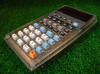 Engineers used clear cases during the development of a product to check if the
electronic and mechanical components fit neatly into the housing before having widely access to 3D design software.
Engineers used clear cases during the development of a product to check if the
electronic and mechanical components fit neatly into the housing before having widely access to 3D design software.
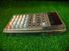 The side view gives you an impression of the upper and lower case shell and the printed circuit boards inside.
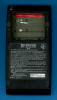
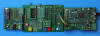
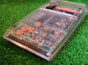 The bottom view gives you (from upper right to lower left) the opening of the rechargeable batteries, the
two calculator chips (TMC0501, TMC0521) and the power supply and clock
generation circuitry.
The bottom view gives you (from upper right to lower left) the opening of the rechargeable batteries, the
two calculator chips (TMC0501, TMC0521) and the power supply and clock
generation circuitry.
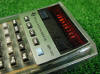
 The display frame covers the upper row of the keys and the two switches neatly. This results in a very valuable design compared to e.g. the later
TI-30.
The display frame covers the upper row of the keys and the two switches neatly. This results in a very valuable design compared to e.g. the later
TI-30.
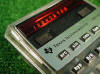
 This amazing pictures gives you an imagination of the curved lens above the red display. Simply a perfect calculator!
Don't miss the SR-50
manufactured for Dismac Industrial S.A. in Brazil changing the layout of the
aluminum bezel.
If you have additions to the above article please email: joerg@datamath.org.
© Joerg Woerner, August 25, 2023. No reprints without written permission.