DATAMATH CALCULATOR MUSEUM
|
DATAMATH CALCULATOR MUSEUM |
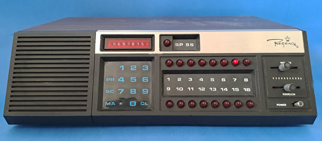
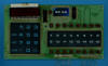
Regency Radio Scanner ACT-T16K "The Touch"
| Date of introduction: | January 1977 | Display technology: | |
| New price: | Display size: | ||
| Size: | 12.5" x 9.47" x
3.9" 315 x 238 x 100 mm3 |
||
| Weight: | 8 lbs, grams | Serial No: | 237-A51938 |
| Batteries: | 13.8 V, 10 VA Mallory 10L123 (1.55 V) |
Date of manufacture: | mth 03 year 1978 |
| AC-Adapter: | 117 V, 18 VA | Origin of manufacture: | USA |
| Precision: | Integrated circuits: | TMS1116, 2*SN99253, many others | |
| Displays: | National Semiconductor NSA578 | ||
| Memories: | |||
| Program steps: | Courtesy of: | Joerg Woerner |
![]()
 Lex,
an avid scanner collector and restorer, HAM radio operator and by profession private mobile radio technician in the Netherlands, contacted the Datamath Calculator Museum in Summer 2023 about the pin-out of certain earlier Texas Instruments single-chip calculator circuits. When in 1976-1977 the first "Computer Radio Scanners" appeared
with Electra's Bearcat 210 (BC-210) and this Regency "The Touch" ACT-T16K on the market, they used for the keyboard and display control calculator chips provided by Texas Instruments.
Lex,
an avid scanner collector and restorer, HAM radio operator and by profession private mobile radio technician in the Netherlands, contacted the Datamath Calculator Museum in Summer 2023 about the pin-out of certain earlier Texas Instruments single-chip calculator circuits. When in 1976-1977 the first "Computer Radio Scanners" appeared
with Electra's Bearcat 210 (BC-210) and this Regency "The Touch" ACT-T16K on the market, they used for the keyboard and display control calculator chips provided by Texas Instruments.
Regency Electronics, Inc. and Texas
Instruments? We heard this before and certainly couldn't resist to dive with Lex deep into radio scanners. Regency was founded in 1945 by former RCA employees Joe Weaver and John Piers in Indianapolis, Indiana as I.D.E.A., Industrial Development Engineering Associates and has a far history in manufacturing electronics. The company was famous to manufacture the World's first commercialized transistor radio in collaboration with Texas Instruments, the Regency
TR-1 of 1954. Through later years, Regency also produced Polaris maritime radios for boats and sea vessels, Citizens Band ("CB") radios and a numerous number of radio scanners.
In the USA, monitoring Police, Fire, Ambulance and other municipal service radio communication was common. At first (1960s) there were hand tuned receivers, looking like normal broadcast receivers with a frequency dial. And one could listen to the one service it was tuned to. But in the late 1960s and early 1970s, Regency (amongst others) manufactured crystal scanners, scanning between 4 to 16, or more channels, to be able to listen to more services on a single radio. And the scanner had no tuning dial; but a row of incandescent lamps that indicate the channels. The channels were scanned automatically the row of lamps, showing a "running light". When radio traffic was received on a channel, it would pause scanning and stay on that channel until the radio traffic ceased, and start scanning the channels again. A small crystal for exact frequency tuning was needed per service to be monitored and it was inserted in a small socket inside the radio. You would need to buy a crystal for each service to be monitored, and crystals were costly, and to install the crystals was a bit technical.
In 1977 Regency built its first crystal less computer scanner "The Touch" ACT-T16K with keyboard, to simply tap in and store in memory the frequencies of the services you wanted to listen to. Buying crystals and placing them inside the scanner was not needed anymore... In that same time frame within a few months, Electra (Bearcat 210), Realistic (PRO-2001) and Tennelec (MCP-1) also introduced their first computer scanners.
The first four Regency scanners shared all a common design language using small 7-digit LED displays borrowed from electronic pocket calculators and the "running light" channel LEDs. The cabinets for these four Regency scanners were made from chipboard with dark brown wood veneer.
By the way, there were crystal less synthesizer scanners manufactured before 1976, and often miscalled computer scanners. But they lacked both a microcomputer, numeric keyboard and LED display, consequently direct frequency programming was not possible. Regency introduced as example the ACT-W10 "WHAMO 10" synthesizer scanner in 1975 with metal combs for digital code frequency selection. There were also synthesizer scanners where you had to enter the row of bits, 0’s and 1’s, one by one with switches into a memory with battery backup, e.g. the Bearcat 101. Or the same principle yet frequency and channels configured with tiny stickers on plastic see through code cards (SBE Opti-Scan 1974). With all of these synthesizer scanners you always had to look up the desired frequency in an extremely large frequency to digital bit code conversion table in the user manual. Without the user manual - and before Google and YouTube - you couldn't set frequencies, hence rendering the product useless.
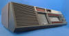
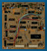
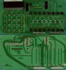
![]() Dismantling the featured "The Touch" ACT-T16K manufactured
around March 1978 by Regency Electronics, Inc. in Indianapolis, Indiana reveals a complex
design with 6 different printed circuit boards (PCBs).
Dismantling the featured "The Touch" ACT-T16K manufactured
around March 1978 by Regency Electronics, Inc. in Indianapolis, Indiana reveals a complex
design with 6 different printed circuit boards (PCBs).
 Lex was kind enough to provide us not only with the pictures
of his ACT-T16K but explaining us the functionality of the individual boards and
sharing the Service Manual with us. Thanks! Radio Scanners are obviously not our
focus and there are excellent websites on the Internet about Radios and Scanners.
Lex was kind enough to provide us not only with the pictures
of his ACT-T16K but explaining us the functionality of the individual boards and
sharing the Service Manual with us. Thanks! Radio Scanners are obviously not our
focus and there are excellent websites on the Internet about Radios and Scanners.
|
• Receiver-PCB: 3 separate varactor
diode tuned frontends for the 30-50 MHz, 146-174 MHz, and 440-512 MHz bands. Including 1st IF filter (10.7 MHz), 2nd IF filter (455kHz), FM discriminator and squelch circuit, power audio amplifier and AC/DC rectifier • VCO-PCB: VCO circuit cast in resin against microphonics, PLL loop-filter and local oscillator • Mixer-PCB: 100 MHz crystal oscillator, frequency multipliers and 100 MHz mixer, all part of the frequency synthesizer. Additional 9V and 5V stabilizers for power supply • Logic-PCB: Regency 501-374 marked "Computer Brain", I/O circuits for keyboards, display and LEDs, PLL synthesizer digital TTL frequency divider circuits for the local oscillator frequency generation and tone decoder circuit • Control-PCB: Touch keypads, calculator type red 7-digit LED display, display drivers and 17 red LEDs • Keyboard-PCB: Volume and squelch slide potentiometers and on/off slide switch |
 Here at the Datamath Calculator Museum we consequently focus on the
the Logic-PCB and the Keyboard-PCB making up the "computer brain" of the Regency
"The Touch" ACT-T16K. Calculator and Radio Scanner sounds like a contradiction,
the first architectures used for electronic calculators used shift registers or
Sequential-Access Memory (SAM) to store the numbers while computers use
Random-Access Memory (RAM) to store information. Integrating SAM on a silicon
chip is much more efficient than integrating RAM allowing for lower costs and
calculators do the math on numbers anyway. Remember how to add two 2-digit
numbers with pencil and paper? Yes, align the numbers so that the tens' and
ones' line up neatly and draw a line under them. Add the digits in the ones'
column together, if the result is larger than 10, add a one to the tens' column.
Finally add the numbers in the tens' column together and if the result is larger
than 100, add a one to the hundreds' result. This is precisely how the first
calculator chips are operating the
TMS1802
single-chip calculator circuit introduced in September 1971 actually uses a
182-bit SAM, organized as 3 Registers * 13 Digits and 2 * 13 Bit-Flags) and a
decimal arithmetic logic unit together with 3,520 Bits Read-Only program Memory
(ROM), organized as 320 Words x 11 Bits. The only math the TMS1802 and its other
siblings from TMS0100 Family can perform are
decimal additions and subtractions on these register, "masking" out unwanted
digits. And multiplications and divisions are just algorithm in the ROM going
back to large numbers of additions and subtractions, respectively. Doing
anything else than decimal additions and subtraction is close to impossible and
Texas Instruments needed a crowbar to connect interface their thermal printer
head technology to a TMS0100 chip for the Canon
Pocketronic II calculator.
Fully aware of the limitations of "Register
Processors", Texas Instruments introduced in October 1974 with the
TMS1000 their first "Digit
Processor"
by replacing the 182-bit Serial-Access Memory with a 256-bit Random-Access
Memory organized as 64 Digits or the equivalent of 4*16-digit Registers and
changing the width of the instructions from 11-bit to 8-bit. The new
architecture allowed to access any 4-bit data memory location with the means of
a pointer gaining a lot of flexibility in digit manipulations bit losing
performance on register operations typically used in electronic calculators.
Here at the Datamath Calculator Museum we consequently focus on the
the Logic-PCB and the Keyboard-PCB making up the "computer brain" of the Regency
"The Touch" ACT-T16K. Calculator and Radio Scanner sounds like a contradiction,
the first architectures used for electronic calculators used shift registers or
Sequential-Access Memory (SAM) to store the numbers while computers use
Random-Access Memory (RAM) to store information. Integrating SAM on a silicon
chip is much more efficient than integrating RAM allowing for lower costs and
calculators do the math on numbers anyway. Remember how to add two 2-digit
numbers with pencil and paper? Yes, align the numbers so that the tens' and
ones' line up neatly and draw a line under them. Add the digits in the ones'
column together, if the result is larger than 10, add a one to the tens' column.
Finally add the numbers in the tens' column together and if the result is larger
than 100, add a one to the hundreds' result. This is precisely how the first
calculator chips are operating the
TMS1802
single-chip calculator circuit introduced in September 1971 actually uses a
182-bit SAM, organized as 3 Registers * 13 Digits and 2 * 13 Bit-Flags) and a
decimal arithmetic logic unit together with 3,520 Bits Read-Only program Memory
(ROM), organized as 320 Words x 11 Bits. The only math the TMS1802 and its other
siblings from TMS0100 Family can perform are
decimal additions and subtractions on these register, "masking" out unwanted
digits. And multiplications and divisions are just algorithm in the ROM going
back to large numbers of additions and subtractions, respectively. Doing
anything else than decimal additions and subtraction is close to impossible and
Texas Instruments needed a crowbar to connect interface their thermal printer
head technology to a TMS0100 chip for the Canon
Pocketronic II calculator.
Fully aware of the limitations of "Register
Processors", Texas Instruments introduced in October 1974 with the
TMS1000 their first "Digit
Processor"
by replacing the 182-bit Serial-Access Memory with a 256-bit Random-Access
Memory organized as 64 Digits or the equivalent of 4*16-digit Registers and
changing the width of the instructions from 11-bit to 8-bit. The new
architecture allowed to access any 4-bit data memory location with the means of
a pointer gaining a lot of flexibility in digit manipulations bit losing
performance on register operations typically used in electronic calculators.
![]()
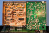
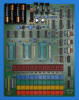
 Inspecting the layout of the Logic-PCB from a Regency "The
Touch" ACT-T16K manufactured around October 1977 based on the
Date codes found on its Integrated Circuits (ICs)
we immediately recognized for the Regency 501-374 marked chip a typical TMS1000
configuration. Preparing our DCM-50A Platform
to allow the Characterization of Single-Chip Calculator Circuits
of the Regency 501-374, we reverse-engineered the relevant parts of the
Logic-PCB and Display-PCB to find out that the ACT-T16K is based on a
TMS1116
chip, a member of the TMS1000 Microcomputer family with increased Instruction
ROM capacity (2,048 Bytes vs. 1,024 Bytes) and RAM size (128 Digits vs. 64
Digits) but fully pin-compatible and hence fitting the right-most TMS1000 Textool
Test Socket of the DCM-50A Platform.
Inspecting the layout of the Logic-PCB from a Regency "The
Touch" ACT-T16K manufactured around October 1977 based on the
Date codes found on its Integrated Circuits (ICs)
we immediately recognized for the Regency 501-374 marked chip a typical TMS1000
configuration. Preparing our DCM-50A Platform
to allow the Characterization of Single-Chip Calculator Circuits
of the Regency 501-374, we reverse-engineered the relevant parts of the
Logic-PCB and Display-PCB to find out that the ACT-T16K is based on a
TMS1116
chip, a member of the TMS1000 Microcomputer family with increased Instruction
ROM capacity (2,048 Bytes vs. 1,024 Bytes) and RAM size (128 Digits vs. 64
Digits) but fully pin-compatible and hence fitting the right-most TMS1000 Textool
Test Socket of the DCM-50A Platform.
![]()
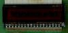
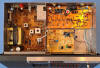
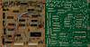
 The layout of the
Keyboard-PCB arranges the 33 "Touch Keys" in a 9*4 matrix using the TMS1116
Outputs R0-R8 and K1, K2, K4, and K8 Inputs while the Squelch Key is read with
Output R9-K2. The anodes of the 7-digit LED Display are connected as in typical
calculator applications to the 8 Segment Outputs O0-O7 of the TMS1116 while the
cathodes use two SN99253 Digit Drivers connected to R0-R6. The 16 discrete
Channel LEDs are connected through Digit Drivers to R7 and R8, leaving the
Search LED on R9. The 7-digit LED display of the reverse-engineered Keyboard-PCB
with the marking NSA578 was manufactured by National Semiconductor and
is a standard components of their NSA500 series of 0.1" (2.54 mm)
non-magnified monolithic LED numeric arrays.
The layout of the
Keyboard-PCB arranges the 33 "Touch Keys" in a 9*4 matrix using the TMS1116
Outputs R0-R8 and K1, K2, K4, and K8 Inputs while the Squelch Key is read with
Output R9-K2. The anodes of the 7-digit LED Display are connected as in typical
calculator applications to the 8 Segment Outputs O0-O7 of the TMS1116 while the
cathodes use two SN99253 Digit Drivers connected to R0-R6. The 16 discrete
Channel LEDs are connected through Digit Drivers to R7 and R8, leaving the
Search LED on R9. The 7-digit LED display of the reverse-engineered Keyboard-PCB
with the marking NSA578 was manufactured by National Semiconductor and
is a standard components of their NSA500 series of 0.1" (2.54 mm)
non-magnified monolithic LED numeric arrays.
The SN99253 Digit Drivers share their
pin-out with the SN75492 but sport on the bottom of the housing a different
96912 marking and we couldn't reveal the meaning of the makings and the exact
chip specifications.
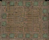 One Integrated Circuit on the Logic-PCB manufactured by
National Semiconductor and marked with a proprietary 310-935-14 marking
caught our attention due to its close proximity to the four Keyboard
Inputs of the TMS1116 and we suspected it to be a MM74C157N Quadruple 2-Line To 1-Line Data Selectors/Multiplexers.
We provided a physical sample of the chip to
Sean Riddle who
de-capped and photographed it. And yes, the die is marked with C157A.
One Integrated Circuit on the Logic-PCB manufactured by
National Semiconductor and marked with a proprietary 310-935-14 marking
caught our attention due to its close proximity to the four Keyboard
Inputs of the TMS1116 and we suspected it to be a MM74C157N Quadruple 2-Line To 1-Line Data Selectors/Multiplexers.
We provided a physical sample of the chip to
Sean Riddle who
de-capped and photographed it. And yes, the die is marked with C157A.
Regency introduced three additional computer scanners after the "The Touch" ACT-T16K based on the same look and feel:
|
• 1978: Digital Flight Scan (ACT-T-720A) - 16 channel only, for monitoring aviation radio traffic (AM modulation) • 1979: Touch K100 (ACT-T-K100) - 10 channel HF/VHF/UHF scanner • 1979: Touch K500 (ACT-T-K500 - 40 channel and 545 pre-programmed frequencies |
In 1980 Regency produced the M100 computer scanner model, succeeded by the M400, both with very different design from the "Touch" and "Flight" models: modern plastic cabinets and green vacuum fluorescent displays.
If you have additions to the above article please email: joerg@datamath.org.
© Lex Steenvoorden and Joerg Woerner, September 3, 2023. No reprints without written permission.