DATAMATH CALCULATOR MUSEUM
|
DATAMATH CALCULATOR MUSEUM |
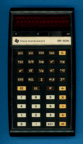
Texas Instruments SR-50A (Version 2)
| Date of introduction: | March 1975 | Display technology: | LED-stick |
| New price: | $109.50 | Display size: | 10 + 2 |
| Size: | 5.8" x 3.2" x
1.3" 147 x 81 x 32 mm3 |
||
| Weight: | 8.5 ounces, 240 grams | Serial No: | 040525 B |
| Batteries: | BP1A | Date of manufacture: | wk 32 year 1976 |
| AC-Adapter: | AC9130, AC9130A | Origin of manufacture: | USA (LTA) |
| Precision: | 13 | Integrated circuits: | TMC0501, TMC0531 |
| Logic: | Sum-of-Products | Displays: | DIS234H |
| Memories: | 1 | ||
| Program steps: | Courtesy of: | Joerg Woerner | |
| Download leaflet: | Download manual: | |
![]()
 The
SR-50A was introduced shortly after the
SR-50 to to reduce manufacturing costs. Later
during production, probably with the introduction of the SR-56,
the SR-50A was revised again. The hardware of both the SR-50A and
SR-51A
was redesigned to accommodate the TMC0501
Arithmetic Chip, one (SR-50A) or two TMC0530
SCOM (Scanning and Read-Only Memory) Chips (SR-51A and SR-56) and none (SR-50A and SR-51A) or one
TMC0599 Multi-Register Chip (SR-56). Here
at the Datamath Calculator Museum we refer to the TMC0530 based SR-50A and
SR-51A calculators as "Version 2", they can easily be recognized with a bold "B"
trailing their serial numbers printed on the label on the back of the
calculators.
The
SR-50A was introduced shortly after the
SR-50 to to reduce manufacturing costs. Later
during production, probably with the introduction of the SR-56,
the SR-50A was revised again. The hardware of both the SR-50A and
SR-51A
was redesigned to accommodate the TMC0501
Arithmetic Chip, one (SR-50A) or two TMC0530
SCOM (Scanning and Read-Only Memory) Chips (SR-51A and SR-56) and none (SR-50A and SR-51A) or one
TMC0599 Multi-Register Chip (SR-56). Here
at the Datamath Calculator Museum we refer to the TMC0530 based SR-50A and
SR-51A calculators as "Version 2", they can easily be recognized with a bold "B"
trailing their serial numbers printed on the label on the back of the
calculators.
Basically the same printed circuit board (PCB) was used
with different chip populations to manufacturer three different calculators priced
between US$ 109.50 and US$ 224.95, and thanks to the power of marketing the most
complex design priced at US$ 179.95 and already featuring the revolutionary
Algebraic Operating
System (AOS™) introduced in September 1975 with the
SR-52 Programmable calculator while the SR-51A priced at US$ 224.95 was
still relying on the outdated
Sum-of-Products (SOP) Logic tracing back to the SR-50.
| Calculator | Logic | Arithmetic Chip |
SCOM Chips |
Multi- Register Chip |
Price |
| SR-50A (V2) | SOP | TMC0501 | TMC0531 | US$ 109.50 | |
| SR-51A (V2) | SOP | TMC0501 | TMC0532 TMC0533 |
US$ 224.95 | |
| SR-56 | AOS | TMC0501 | TMC0537 TMC0538 |
TMC0599 | US$ 179.95 |
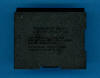
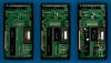
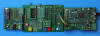
 Dismantling the featured SR-50A
(Version 2) calculator with Date code LTA 3276 and manufactured in August 1976 in
Lubbock, Texas and comparing with an SR-50A (Version 1)
calculator manufactured three months earlier in Italy reveals some unexpected
changes. While the earlier calculator uses a SN97227 Clock Generator Chip in a
small 8-pin DIP (Dual In-line Package with a 0.1” / 2.54 mm lead pitch) housing
together with a TP4011A Clock Buffer Chip
in a 14-pin DIP housing to reduce both real estate on the PCB and manufacturing
costs compared to the original SR-50 introduced in January 1974, are these two
Integrated Circuits (ICs) gone. And no, they are not hiding under the small
power supply module on the right side of the PCB boosting the output of the
rechargeable
BP1A
Battery Pack to the required voltages of the calculator electronics.
Dismantling the featured SR-50A
(Version 2) calculator with Date code LTA 3276 and manufactured in August 1976 in
Lubbock, Texas and comparing with an SR-50A (Version 1)
calculator manufactured three months earlier in Italy reveals some unexpected
changes. While the earlier calculator uses a SN97227 Clock Generator Chip in a
small 8-pin DIP (Dual In-line Package with a 0.1” / 2.54 mm lead pitch) housing
together with a TP4011A Clock Buffer Chip
in a 14-pin DIP housing to reduce both real estate on the PCB and manufacturing
costs compared to the original SR-50 introduced in January 1974, are these two
Integrated Circuits (ICs) gone. And no, they are not hiding under the small
power supply module on the right side of the PCB boosting the output of the
rechargeable
BP1A
Battery Pack to the required voltages of the calculator electronics.
![]()
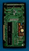
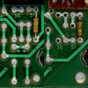
![]() The
secret sauce of the revised design is the new TMC0531 SCOM Chip replacing the
TMC0521 of the original SR-50 and SR-50A
(Version 1) featuring an integrated Clock Generator for the TMC0501 Arithmetic
Chip and the optional TMC0599 Multi-Register Chip used with the SR-56.
The
secret sauce of the revised design is the new TMC0531 SCOM Chip replacing the
TMC0521 of the original SR-50 and SR-50A
(Version 1) featuring an integrated Clock Generator for the TMC0501 Arithmetic
Chip and the optional TMC0599 Multi-Register Chip used with the SR-56.
![]() Other
areas of the PCB didn't change that dramatically, we still identify the two SN27882
display drivers known from the previous designs of the calculator.
Other
areas of the PCB didn't change that dramatically, we still identify the two SN27882
display drivers known from the previous designs of the calculator.
![]()
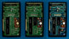
 Comparing the PCBs of the three siblings SR-50A
(Version 2), SR-51A (Version 2), and
SR-56 (in TI internal documents
often dubbed SR-51P for Programmable)
reveals some very subtle differences, too. Right below the power
supply module for the internal calculator voltages VDD (-10.0 Volts) and VGG (-15.8 Volts) you'll find a 50 and
a 51 marking.
Depending on the calculator model three configurations are populated:
Comparing the PCBs of the three siblings SR-50A
(Version 2), SR-51A (Version 2), and
SR-56 (in TI internal documents
often dubbed SR-51P for Programmable)
reveals some very subtle differences, too. Right below the power
supply module for the internal calculator voltages VDD (-10.0 Volts) and VGG (-15.8 Volts) you'll find a 50 and
a 51 marking.
Depending on the calculator model three configurations are populated:
|
• SR-50A: A 150 kOhm resistor
soldered into the left (50) position connects the CLK pin and VGG
of the TMC0531 to enable its internal clock generator and providing the
two non-overlapping clock signals with 180° phase difference and a frequency around 180 kHz to the TMC0501 Arithmetic Chip • SR-51A: A 150 kOhm resistor soldered into the right (51) position connects the CLK pin and VGG of the TMC0533 to enable its internal clock generator and providing the two non-overlapping clock signals with 180° phase difference and a frequency around 180 kHz to the TMC0501 Arithmetic Chip. The clock generator of the TMC0532 is disabled and it generates the D0 signal instead for possible PC-100 Printer Cradle compatibility • SR-56: A 30 kOhm soldered into the right (51) position connects the CLK pin and VGG of the TMC0538 to enable its internal clock generator, a 39 pF capacitor between the CLK pin and VSS greatly improves the stability of the clock frequency. The clock generator of the TMC0537 is disabled and it generates the D0 signal for PC-100 Printer Cradle compatibility |
In the lower-left area of the PCBs you'll notice a small symbol for a diode but only the SR-56 has actually a diode soldered into the position, both the SR-50A and SR-51A are using a piece of wire, instead. From a technical point of view the diode is necessary for operation of the calculator on a PC-100 Printer Cradle. While the Key input matrix line KP of the TMC0501 Arithmetic Chip is used in stand-alone calculator mode for various keys (D1, D2, D3, D4, D6, D7, and D13), doubles it in the PC-100 Printer Cradle application to signal three additional conditions or actions:
|
• D0: Presence detection of PC-100 Printer Cradle • D12: [PRINT] key detection • D15: [TRACE] switch detection |
The SR-56 uses a second set of diodes and current limiting resistors for the charging circuitry of its battery pack to accommodate for the increased power consumption of the calculator due to the TMC0599 Multi-Register Chip compared to the SR-51.
Last but not least features only the SR-56 gold-plated contacts for the PC-100 Printer Cradle.
 As
of today we know two revisions of the consolidated PC used with the SR-50A
(Version 2), SR-51A (Version 2) and SR-56 but noticed only one minor change in
the "Clock Generator Patch Area". The unused wiring positions in the lower area
of the PCB were removed to free up some space for the slightly larger power
supply module. The picture on the right compares the relevant part of the PCB
from two SR-51A calculators manufactured in April 1976 and November 1976.
As
of today we know two revisions of the consolidated PC used with the SR-50A
(Version 2), SR-51A (Version 2) and SR-56 but noticed only one minor change in
the "Clock Generator Patch Area". The unused wiring positions in the lower area
of the PCB were removed to free up some space for the slightly larger power
supply module. The picture on the right compares the relevant part of the PCB
from two SR-51A calculators manufactured in April 1976 and November 1976.
 Comparing
the Constant ROM Content with
the programmed constants frequently used with computing algorithm of
trigonometric functions like sine, cosine, or tangent of an SR-50 manufactured in
May 1974 still using the original TMC0521-2 SCOM Chip with the TMC0531A Chip
of the featured SR-50A (Version 2) with our
TMS0500 Platform after recording their
ROM Images showed no
differences.
Comparing
the Constant ROM Content with
the programmed constants frequently used with computing algorithm of
trigonometric functions like sine, cosine, or tangent of an SR-50 manufactured in
May 1974 still using the original TMC0521-2 SCOM Chip with the TMC0531A Chip
of the featured SR-50A (Version 2) with our
TMS0500 Platform after recording their
ROM Images showed no
differences.
If you have additions to the above article please email: joerg@datamath.org.
© Joerg Woerner, September 10, 2008. No reprints without written permission.