DATAMATH CALCULATOR MUSEUM
|
DATAMATH CALCULATOR MUSEUM |
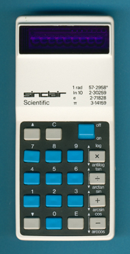
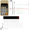
Sinclair Scientific
| Date of introduction: | May 1974 | Display technology: | LED-stick |
| New price: | Display size: | 5 + 2 | |
| Size: | 4.4" x 2.0" x 0.7" 112 x 51 x 18 mm3 |
||
| Weight: | 3.9 ounces, 58 grams | Serial No: | 706465 |
| Batteries: | 4*AAA Alkaline | Date of manufacture: | mth 10 year 1975 |
| AC-Adapter: | Origin of manufacture: | United Kingdom | |
| Precision: | 6 | Integrated circuits: | TMC0805, IFC1, IFC2 |
| Logic: | Polish Notation | Displays: | Bowmar Optostic |
| Memories: | 1 | ||
| Program steps: | Courtesy of: | Joerg Woerner | |
| Download manuals: | |
![]()
 Sinclair
Radionics Ltd founded on July 25, 1961 by Sir Clive Sinclair († September 16, 2021) in
Cambridge, England, launched with the Scientific in May 1974 a highly unusual
12-function calculator. It displays only in scientific notation - 5 digit mantissa, 2 digit exponent. Because of the way its
software is designed, it relies on RPN (Reverse Polish
Notation) like
the famous Hewlett Packard HP-35
introduced in July 1972. This unusual method of mathematical problem solving meant that, for instance, to add 2 and 4, one had to enter 2,
then [+] symbol, then 4, finally the
[+] symbol. There is no [=] key.
Sinclair
Radionics Ltd founded on July 25, 1961 by Sir Clive Sinclair († September 16, 2021) in
Cambridge, England, launched with the Scientific in May 1974 a highly unusual
12-function calculator. It displays only in scientific notation - 5 digit mantissa, 2 digit exponent. Because of the way its
software is designed, it relies on RPN (Reverse Polish
Notation) like
the famous Hewlett Packard HP-35
introduced in July 1972. This unusual method of mathematical problem solving meant that, for instance, to add 2 and 4, one had to enter 2,
then [+] symbol, then 4, finally the
[+] symbol. There is no [=] key.
Texas Instruments announced on September 17, 1971 with the TMS1802NC the first available standard calculator building block on a chip, it was later renamed into TMS0102. The chip integrates 3,520 Bits Read-Only program Memory (ROM, 320 Words x 11 Bits), a 182-bit Serial-Access Memory (SAM, 3 Registers * 13 Digits, 2 * 13 Bit-Flags) and a decimal arithmetic logic unit as well as control, timing, and output decoders but no drivers for the display. These function blocks of the chip add up to an overall complexity of roughly 5,000 transistors and marked in 1971 with its die size of roughly 230 mils * 230 mils (6 mm * 6 mm) the limits of a chip for commercial manufacturing.
While the 3-Register Serial-Access Memory of the TMS0100 series of single-chip calculator circuits is large enough to realize a basic four-function calculator with independent memory, couldn't fit the engineers the necessary code for a simple Memory function into the 320-Word Read-Only program Memory of the device and Texas Instrument started to manufacture in 1973 calculators like the Montgomery Ward P8M with chips from their competitor Western Digital.
 With the the numbers of transistors in Large-scale Integration
(LSI) chips roughly doubling every two years, Texas Instruments decided
for the successor of the TMS0100 family to expand into three
different branches:
With the the numbers of transistors in Large-scale Integration
(LSI) chips roughly doubling every two years, Texas Instruments decided
for the successor of the TMS0100 family to expand into three
different branches:
|
•
TMS0600: Increased ROM (384 Words
* 11 Bits), Identical SAM (13 Digits Registers), external display drivers. Process shrink, higher functionality • TMS0700: Identical ROM (320 Words * 11 Bits), Identical SAM (13 Digits Registers), external display drivers. Process shrink, identical functionality, cost reduction of IC • TMS0800: Identical ROM (320 Words * 11 Bits), Reduced SAM (11 Digits Registers), integrated segment drivers. Process shrink, reduced functionality, higher integration |
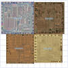
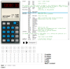
 On our quest to
Record the ROM
Content of the TMC0805 single-chip calculator circuit, we acquired a
Sinclair Scientific in England (Thank you, Adam!) and studied its electronic
circuitry completely. Disassembling the donor calculator with serial number
#706465 and manufactured in October 1975 in United Kingdom reveals a surprisingly compact design with just one printed
circuit board (PCB) for its main electronics and keyboard, with the display module
soldered directly to it and powered by
four AAA-sized disposable Alkaline batteries. The Main-PCB is centered around a
Texas Instruments single-chip calculator circuit and supported by two
full-custom Integrated Circuits (ICs) and a few discrete components:
On our quest to
Record the ROM
Content of the TMC0805 single-chip calculator circuit, we acquired a
Sinclair Scientific in England (Thank you, Adam!) and studied its electronic
circuitry completely. Disassembling the donor calculator with serial number
#706465 and manufactured in October 1975 in United Kingdom reveals a surprisingly compact design with just one printed
circuit board (PCB) for its main electronics and keyboard, with the display module
soldered directly to it and powered by
four AAA-sized disposable Alkaline batteries. The Main-PCB is centered around a
Texas Instruments single-chip calculator circuit and supported by two
full-custom Integrated Circuits (ICs) and a few discrete components:
|
• Calculating Unit -
TMC0805 single-chip calculator circuit • Display Driver - No Segment Drivers, IFC1/IFC2 Digit Drivers • TMC0805 internal Clock signal generation • IFC2 DC/DC converter with transformer • 17-pin wiring to the LED Display-Module |
 Calculating Unit: The
Sinclair Scientific makes use of the TMC0805 single-chip calculator circuit derived from the TMS1802,
better known as first "calculator-on-a-chip" but with a Serial-Access
Memory decreased from 13 Digit Registers to 11 Digit Registers while keeping the Read-Only program Memory
of 320 Words x 11 Bits and integrating Segment Drivers. The first designs of the
TMS0800 architecture could be found with
the TI-1500 introduced in April 1974 and using the TMS0803 chip, while both
Canon LE-84 and Sinclair Cambridge introduced in
May 1974 are centered around the TMS0801
chip.
Calculating Unit: The
Sinclair Scientific makes use of the TMC0805 single-chip calculator circuit derived from the TMS1802,
better known as first "calculator-on-a-chip" but with a Serial-Access
Memory decreased from 13 Digit Registers to 11 Digit Registers while keeping the Read-Only program Memory
of 320 Words x 11 Bits and integrating Segment Drivers. The first designs of the
TMS0800 architecture could be found with
the TI-1500 introduced in April 1974 and using the TMS0803 chip, while both
Canon LE-84 and Sinclair Cambridge introduced in
May 1974 are centered around the TMS0801
chip.
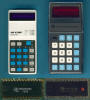
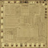
![]() While Texas Instruments introduced with the
SR-10 in November 1972 a "Slide Rule"
calculator with just [1/x], [x2], [sqr X] functionality and
scientific notation into the 320-Word ROM of the TMS0120, cramped the engineers
of Sinclair in Summer 1974 eight trigonometric and logarithm functions into the
320-Word ROM of the TMC0805. Learn more about "How could they do it,
how could they?".
While Texas Instruments introduced with the
SR-10 in November 1972 a "Slide Rule"
calculator with just [1/x], [x2], [sqr X] functionality and
scientific notation into the 320-Word ROM of the TMS0120, cramped the engineers
of Sinclair in Summer 1974 eight trigonometric and logarithm functions into the
320-Word ROM of the TMC0805. Learn more about "How could they do it,
how could they?".
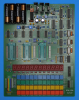
![]() Display: The featured Sinclair Scientific manufactured in
October 1975 makes use of a full-custom Bowmar Optostic Nine-Digit display module with 9 Seven-Segment
displays chips bonded onto a PCB and magnified with a clear plastic lens. The
display module is connected with 17 short jumper wires directly to the Main-PCB.
The Sinclair Scientific uses fixed decimal point scientific notation and the
number '50' as an example is displayed as '5.0000 E01'. Consequently is the
decimal point of the display module is hardwired between the first and second
position of the mantissa.
Display: The featured Sinclair Scientific manufactured in
October 1975 makes use of a full-custom Bowmar Optostic Nine-Digit display module with 9 Seven-Segment
displays chips bonded onto a PCB and magnified with a clear plastic lens. The
display module is connected with 17 short jumper wires directly to the Main-PCB.
The Sinclair Scientific uses fixed decimal point scientific notation and the
number '50' as an example is displayed as '5.0000 E01'. Consequently is the
decimal point of the display module is hardwired between the first and second
position of the mantissa.
![]() Display Driver: The Main-PCB of the featured Scientific
manufactured in October 1975 makes use of nine Digit Drivers for the LED display
integrated into full-custom ICs IFC1 and
IFC2 manufactured by Texas Instruments while the TMC0805 chip
drives the Segments directly. The IFC1 integrates seven NPN bipolar junction
transistors (BJTs) in common-emitter topology with the base of the transistors
directly connected to input pins and each complemented with a pull-down resistor
to VDD to allow the scanning of the keyboard matrix of the
calculator. To limit the segment currents of the LED display chips,
common-emitter pin of the digit drivers is connected with a 100 Ohm resistor to
the negative battery terminal, resulting in a maximum digit current of about 35
mA. With the numbers '0' to '9' illuminating on average five segments, the
typical peak current per segment is 7 mA. The two remaining NPN BJTs are
integrated into the IFC2 chip.
Display Driver: The Main-PCB of the featured Scientific
manufactured in October 1975 makes use of nine Digit Drivers for the LED display
integrated into full-custom ICs IFC1 and
IFC2 manufactured by Texas Instruments while the TMC0805 chip
drives the Segments directly. The IFC1 integrates seven NPN bipolar junction
transistors (BJTs) in common-emitter topology with the base of the transistors
directly connected to input pins and each complemented with a pull-down resistor
to VDD to allow the scanning of the keyboard matrix of the
calculator. To limit the segment currents of the LED display chips,
common-emitter pin of the digit drivers is connected with a 100 Ohm resistor to
the negative battery terminal, resulting in a maximum digit current of about 35
mA. With the numbers '0' to '9' illuminating on average five segments, the
typical peak current per segment is 7 mA. The two remaining NPN BJTs are
integrated into the IFC2 chip.
 Power Supply: The Sinclair Scientific is powered by four AAA-sized disposable Alkaline batteries
and uses a DC/DC Converter of the full-custom IC IFC2 to generate the necessary supply voltages for the
electronics. The DC/DC Converter of the IFC2 chip integrates the switching
transistor and drives directly the coil of the transformer used to
generate the two negative voltages VDD (-9.5 V) and VGG (-15.0 V). The VDD voltage is fed back to the IFC2 and used to regulate it to its
nominal value of -9.5 V. The VGG voltage is not individually regulated but
directly proportional to the VDD voltage due to the transformer
design. The design is using pulse-width modulation (PWM) in its control
loop with a nominal frequency of about 750 kHz to allow for a small
transformer.
Power Supply: The Sinclair Scientific is powered by four AAA-sized disposable Alkaline batteries
and uses a DC/DC Converter of the full-custom IC IFC2 to generate the necessary supply voltages for the
electronics. The DC/DC Converter of the IFC2 chip integrates the switching
transistor and drives directly the coil of the transformer used to
generate the two negative voltages VDD (-9.5 V) and VGG (-15.0 V). The VDD voltage is fed back to the IFC2 and used to regulate it to its
nominal value of -9.5 V. The VGG voltage is not individually regulated but
directly proportional to the VDD voltage due to the transformer
design. The design is using pulse-width modulation (PWM) in its control
loop with a nominal frequency of about 750 kHz to allow for a small
transformer.
Here at the Datamath Calculator Museum we usually measure during our "Teardown" of a calculator the operating current with both a '0.' and '88888888.' shown on the display, to calculate its balance between "idle current" and 'display current'. This approach doesn't work with the Sinclair Scientific, after power-on the display is showing '0.0000 00'. We decided to use the direct approach with digital multimeter and oscilloscope and noticed immediately that the operating currents of the featured Sinclair Scientific displaying '1.1111 11' and '8.8888 88' are identical:
| Mode | Display | Current VBAT = 6.0 V |
Clock Frequency |
| Calculating | 1.1111 11 | 35 mA | 130 kHz |
| Calculating | 8.8888 88. | 35 mA | 130 kHz |
Studying the schematics of the Sinclair Scientific from its Assembly Instructions explains this observation easily. The design is not limiting the segment current per LED chip, it is limiting its digit current, instead. A simple 100 Ohm resistor between the common-emitter of the IFC1 chip and the negative battery terminal limits the digit current to around 35 mA when operated with 6 Volt nominal battery voltage:
| • TMC0805 segment driver (0.6 V) - LED chip (1.7 V) - digit driver (0.1 V) - 100 Ohm resistor (3.5 V) |
The IFC1 is driving only seven of the nine digits of the LED module and the IFC2 is responsible for the two other digits and using a similar approach to limit the digit currents. The main difference between the two solutions lies in the position of the resistors. While the IFC1 is using a single resistor connected to its ground (emitter) pin, uses the IFC2 two discrete resistors connected to each of its two output (collector) pin. One output of the IFC2 chip, connected to the minus sign of the exponent, is using a 470 Ohm resistor, while the other output driving the 10s digit of the exponent is using a 100 Ohm resistor.

 Keyboard: The keyboard of the Sinclair Scientific uses
short-travel keys to push small metal discs against
two contacts etched on the Main-PCB. A separator plate keeps the metal plate
holding the discs isolated from the electronics of the calculator.
Keyboard: The keyboard of the Sinclair Scientific uses
short-travel keys to push small metal discs against
two contacts etched on the Main-PCB. A separator plate keeps the metal plate
holding the discs isolated from the electronics of the calculator.
The Sinclair Scientific calculator was sold as a Build-It-Yourself kit, too. The Scientific Programmable was an advanced version launched in 1977, again using reverse Polish notation. It could handle programs of up to 24 steps and cost £29.95.
"How could they do it, how could they?": The TMS0800 family of single-chip calculators was developed with cost optimized Four-Banger calculators like theTI-1500 in mind and supported consequently only 3,520 Bits Read-Only program Memory (ROM, 320 Words x 11 Bits), a 154-bit Serial-Access Memory (SAM, 3 Registers * 11 Digits, 2 * 11 Bit-Flags) and a decimal arithmetic logic unit as well as control, timing, and output decoders plus segment drivers for the 9-Digit LED display resulting in just about 5,000 transistors on a die with a size of 205 mils * 200 mils / 5.2 mm * 5.1 mm. At first glance not enough resources for a 12-function Scientific calculator but Clive Sinclair used a secret weapon - programming whiz and math PhD Nigel Searle.
 Ken Shirriff studied the United
States Patent Application
US3934233A
describing the TMS0800 architecture and the program code used with the
TI-1500 very carefully and was
able to create a JavaScript Simulator
for the TMS0800 simulating a (slightly modified)
TI-2500-II.
Ken Shirriff studied the United
States Patent Application
US3934233A
describing the TMS0800 architecture and the program code used with the
TI-1500 very carefully and was
able to create a JavaScript Simulator
for the TMS0800 simulating a (slightly modified)
TI-2500-II.
 Ken learned in 2013 about
the Sinclair Scientific and when
John McMaster was in 2014 able to successfully decap a TMC0805 single-chip
calculator circuit and retrieving its 3,520 Bits of Program Code, the Miracle of the Sinclair Scientific was solved.
Well, it took Ken countless hours to figure it out. Thanks!
Ken learned in 2013 about
the Sinclair Scientific and when
John McMaster was in 2014 able to successfully decap a TMC0805 single-chip
calculator circuit and retrieving its 3,520 Bits of Program Code, the Miracle of the Sinclair Scientific was solved.
Well, it took Ken countless hours to figure it out. Thanks!
Please read more on Ken's blog
Reversing Sinclair's amazing 1974 calculator hack - half the ROM of the HP-35.
 With
the DCM-50A Platform developed to
Characterize and
Reverse-engineer
Single-chip Calculator Circuits we could proof that the
Program Code of the TM0805
manually extracted by John some 10 years ago from a bare die is 100% accurate.
With
the DCM-50A Platform developed to
Characterize and
Reverse-engineer
Single-chip Calculator Circuits we could proof that the
Program Code of the TM0805
manually extracted by John some 10 years ago from a bare die is 100% accurate.
If you have additions to the above article please email: joerg@datamath.org.
© Joerg Woerner, December 5, 2001. No reprints without written permission.