DATAMATH CALCULATOR MUSEUM
|
DATAMATH CALCULATOR MUSEUM |
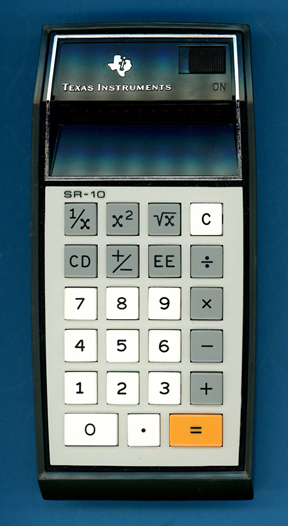
Texas Instruments SR-10 Version 3
| Date of introduction: | January 1975 | Display technology: | LED modules + lens |
| New price: | Display size: | 8 + 2 | |
| Size: | 6.3" x 3.1" x
1.5" 158 x 78 x 38 mm3 |
||
| Weight: | 9.2 ounces, 262 grams | Serial No: | 947828 |
| Batteries: | 3*AA NiCd | Date of manufacture: | wk 20 year 1975 |
| AC-Adapter: | AC9130 | Origin of manufacture: | USA |
| Precision: | 8 | Integrated circuits: | TMS0120 (TMS0720), 2*SN75494, SN27931 |
| Logic: | Chain | Displays: | DIS115F (12*DISXXX) |
| Memories: | |||
| Program steps: | Courtesy of: | Joerg Woerner | |
| Download manuals: | |
![]()
![]() With
the Calculator War starting in 1975 and the subsequent dramatic price decline
for basic four-function calculators, Texas Instrument was far-sighted and knew
about the vulnerability of their SR-10 introduced already in November 1972 and
started in 1974 a cost-reduction program for it. The revised SR-10 was
introduced in January 1975, just a few months before its discontinuation.
With
the Calculator War starting in 1975 and the subsequent dramatic price decline
for basic four-function calculators, Texas Instrument was far-sighted and knew
about the vulnerability of their SR-10 introduced already in November 1972 and
started in 1974 a cost-reduction program for it. The revised SR-10 was
introduced in January 1975, just a few months before its discontinuation.
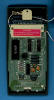
 Dismantling the featured SR-10 Version 3 with Date code
205 and manufactured in May 1975 in the United States reveals a complex design with three printed circuit boards (PCBs) for main electronics, display, and keyboard powered by three AA-sized rechargeable NiCd batteries. The
only visible changes to an SR-10 Version 2 are a
revised Main-PCB with only two instead of four display drivers and most of
discrete components for clock generation and power supply replaced with an
Integrated Circuit (IC):
Dismantling the featured SR-10 Version 3 with Date code
205 and manufactured in May 1975 in the United States reveals a complex design with three printed circuit boards (PCBs) for main electronics, display, and keyboard powered by three AA-sized rechargeable NiCd batteries. The
only visible changes to an SR-10 Version 2 are a
revised Main-PCB with only two instead of four display drivers and most of
discrete components for clock generation and power supply replaced with an
Integrated Circuit (IC):
|
• Calculating Unit - TMS0120 single-chip calculator circuit • Display Driver - 2*SN75494 Digit Drivers • Support Chip - SN27931 for clock signal generation for TMS0120 and power converter with transformer • 21-pin connector to the Display-PCB • 15-pin connector to the Keyboard-PCB |
![]()
![]() Calculating Unit: The
SR-10 makes use of the TMS0120 single-chip calculator circuit derived from the TMS1802,
better known as first "calculator-on-a-chip". Around July 1973 the first TMS0100 designs were ported to an 8-micron process and internally renamed to
TMS0700 but still marked on the outside of the package with TMS01XX. The
featured SR-10 Version 3 manufactured in May 1975 uses according to its
marking on the bottom of the package a TMS0720.
Calculating Unit: The
SR-10 makes use of the TMS0120 single-chip calculator circuit derived from the TMS1802,
better known as first "calculator-on-a-chip". Around July 1973 the first TMS0100 designs were ported to an 8-micron process and internally renamed to
TMS0700 but still marked on the outside of the package with TMS01XX. The
featured SR-10 Version 3 manufactured in May 1975 uses according to its
marking on the bottom of the package a TMS0720.
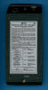
![]() Display: The featured SR-10 manufactured in
May 1975 uses a
DIS115F Twelve-Digit display module with 12 individual DISXXX Seven-Segment displays and an integrated magnifying lens.
Display: The featured SR-10 manufactured in
May 1975 uses a
DIS115F Twelve-Digit display module with 12 individual DISXXX Seven-Segment displays and an integrated magnifying lens.
![]() Display Driver: The Main-PCB of the featured SR-10 manufactured in
May 1973 makes use of only two Display Drivers. The two
SN75493 Segment Drivers for four segments, each
from its predecessor were replaced by the internal drivers of the TMS0120 chip.
The two
SN75494 Digit Drivers for six digits, each are improvements of the original
SN75491/SN75492
chips introduced with the TMS1802 but allow for operation at lower voltages. The
SN75494 feature an additional marking "27914", we assume that it refers to some
additional testing of the chips for tighter specifications necessary with the
SR-10 design.
Display Driver: The Main-PCB of the featured SR-10 manufactured in
May 1973 makes use of only two Display Drivers. The two
SN75493 Segment Drivers for four segments, each
from its predecessor were replaced by the internal drivers of the TMS0120 chip.
The two
SN75494 Digit Drivers for six digits, each are improvements of the original
SN75491/SN75492
chips introduced with the TMS1802 but allow for operation at lower voltages. The
SN75494 feature an additional marking "27914", we assume that it refers to some
additional testing of the chips for tighter specifications necessary with the
SR-10 design.
![]() Clock: The SR-10
Version 3 introduced the approach of a dynamic
switching of the clock frequency for the TMS0100 single-chip calculator circuit
introduced to conserve power between calculations. The astable multivibrator
integrated in the SN27931 Support Chip idles at a frequency of around
50 kHz but increases with the detection of a depressed keybutton for a short time to about 200 kHz to reduce execution time of the operations.
Three diodes are connected between the keymatrix inputs KN (numbers), KO
(operations) and KP ([1/x],
[x2] and [sqr X]) and the SN27931 to catch every entry of a number or
function keys. The resulting power savings are impressive and we observed with the
featured SR-10 manufactured in May 1975 a current reduction of up to 40% in
idle mode.
Clock: The SR-10
Version 3 introduced the approach of a dynamic
switching of the clock frequency for the TMS0100 single-chip calculator circuit
introduced to conserve power between calculations. The astable multivibrator
integrated in the SN27931 Support Chip idles at a frequency of around
50 kHz but increases with the detection of a depressed keybutton for a short time to about 200 kHz to reduce execution time of the operations.
Three diodes are connected between the keymatrix inputs KN (numbers), KO
(operations) and KP ([1/x],
[x2] and [sqr X]) and the SN27931 to catch every entry of a number or
function keys. The resulting power savings are impressive and we observed with the
featured SR-10 manufactured in May 1975 a current reduction of up to 40% in
idle mode.
A similar circuitry was introduced in August 1973 for the TI-2500 Datamath calculator with the introduction of the TI-2500 Version 3 but using only two diodes for the KN and KO lines.
Power Supply: The SR-10 is powered by three AA-sized rechargeable NiCd batteries resulting in a typical voltage between 3.0 V (completely depleted cells) and 4.5 V (while charging full cells). The Main-PCB hosts a power converter circuit centered around the SN27931 and a step-up transformer with various diodes and capacitors to generate the supply voltages for the TMS0120 and display.
Battery Saver Circuit: To save battery power the LED display turns off automatically between 15 and 60 seconds after the last keyboard entry, except for the first digit (Digit D3 of TMS0120, LSD of Mantissa). If the display turns off while entering a problem, the display turns on automatically with the first keyboard entry. Depressing the [=] key brings back the last calculated display. The SN27931 Support Chip makes use of the three diodes to detect depressed keybuttons to trigger an integrated monoflop to keep the Digit Drivers enabled. If the monoflop time expires, the Digit Drivers sans Digit 3 are disabled and the clock frequency of the TMS0720 is already reduced for an impressive reduction of power consumption:
| Mode | Display | Current VBAT = 4.5 V |
Clock Frequency |
| Idle | 0 | 48 mA | 45 kHz |
| Calculating | 0 | 68 mA | 200 kHz |
| Power Save | 0 | 32 mA | 45 kHz |
| Idle | E88888888-88 | 126 mA | 45 kHz |
| Calculating | E88888888-88 | 145 mA | 200 kHz |
| Power Save | 8 | 83 mA | 45 kHz |
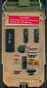
Keyboard: The Klixon™ type keyboard looks very similar to the Datamath calculator with some additional keys placed in the upper line. Later calculators like the SR-11 changed the style of the keys but kept the extreme wedge-style of the housing that was adopted for the scientific desktop calculators SR-20 and SR-22, too. The last portable scientific calculator with this wedge-design was introduced in October 1974 with the SR-16.
![]() The first series of the SR-10
shared the poor readability
of the TIL360
based
display with the early Datamath calculators.
The first series of the SR-10
shared the poor readability
of the TIL360
based
display with the early Datamath calculators.
![]() Texas
Instruments experimented with different solutions and created some prototypes
with lenses attached to the 6-digit LED-modules.
Texas
Instruments experimented with different solutions and created some prototypes
with lenses attached to the 6-digit LED-modules.
Later models used different LED-modules with an additional magnification lens.
Don't miss the rare SR-10 Clear-Case Prototype and
compare it with the SR-10 Version 2.
Not only the appearance of the SR-10 and the used LED-modules changed during the life cycle of the calculator, a later cost-reduction redesign changed the Main-PCB completely and we differentiate between four different SR-10 Versions manufactured in the United States between November 1972 and June 1975:
| Version | Position of SR-10 logo |
Display Type |
Display Driver |
| SR-10 USA V1 | Display frame | 6-digit modules without lens |
4 ICs |
| SR-10 USA V1D2 | Display frame | single modules with lens |
4 ICs |
| SR-10 USA V2 | Keyboard | single modules with lens |
4 ICs |
| SR-10 USA V3 | Keyboard | single modules with lens |
2 ICs |
Here at the Datamath Calculator Museum we classify the featured SR-10 as Display Frame Version 2, PCB Type 3 and Display Type 2.
 Compare the
internals of an SR-10 Version 3 with an SR-16
from the same timeframe.
Compare the
internals of an SR-10 Version 3 with an SR-16
from the same timeframe.
If you have additions to the above article please email: joerg@datamath.org.
© Joerg Woerner, July 5, 2002. No reprints without written permission.