DATAMATH CALCULATOR MUSEUM
|
DATAMATH CALCULATOR MUSEUM |
Texas Instruments SR-50A (Version 1)
| Date of introduction: | March 1975 | Display technology: | LED-stick |
| New price: | $109.50 | Display size: | 10 + 2 |
| Size: | 5.8" x 3.2" x
1.3" 147 x 81 x 32 mm3 |
||
| Weight: | 8.5 ounces, 240 grams | Serial No: | 8054507 |
| Batteries: | BP1A | Date of manufacture: | wk 22 year 1976 |
| AC-Adapter: | AC9130, AC9130A | Origin of manufacture: | Italy (RCI) |
| Precision: | 13 | Integrated circuits: | TMC0501, TMC0521, SN97227 |
| Logic: | Sum-of-Products | Displays: | DIS234G |
| Memories: | 1 | ||
| Program steps: | Courtesy of: | Joerg Woerner | |
| Download leaflet: | Download manual: | |

![]() The
SR-50A was introduced shortly after the SR-50 to to reduce manufacturing costs.
The only advantage compared to
early SR-50 calculators is the higher calculating precision. Please find the
comparison in the Calculator forensics.
The
SR-50A was introduced shortly after the SR-50 to to reduce manufacturing costs.
The only advantage compared to
early SR-50 calculators is the higher calculating precision. Please find the
comparison in the Calculator forensics.
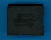
 Dismantling the featured SR-50A calculator with
Date code 2276 RCI and manufactured in May 1976 in
Rieti, Italy reveals a surprise - the printed circuit board (PCB) is still using
the original "Version 1" layout while calculators manufactured in the US during
the same time used already the design known here at the Datamath Calculator
Museum as SR-50A (Version 2). Compared to the first
generation SR-50 introduced already in January 1974 the internal construction
was changed completely, the electronics previously distributed over two PCBs is
now consolidated on one larger PCB and the electric contacts for the rechargeable
BP1A
Battery Pack using three AA-sized NiCd cells are part of that PCB, too.
Dismantling the featured SR-50A calculator with
Date code 2276 RCI and manufactured in May 1976 in
Rieti, Italy reveals a surprise - the printed circuit board (PCB) is still using
the original "Version 1" layout while calculators manufactured in the US during
the same time used already the design known here at the Datamath Calculator
Museum as SR-50A (Version 2). Compared to the first
generation SR-50 introduced already in January 1974 the internal construction
was changed completely, the electronics previously distributed over two PCBs is
now consolidated on one larger PCB and the electric contacts for the rechargeable
BP1A
Battery Pack using three AA-sized NiCd cells are part of that PCB, too.
![]()
![]()
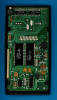 The
Main-PCB of the SR-50A is still centered
around the "Calculator Brain" composed of the two
TMC0501 Arithmetic and
TMC0521 Scanning and Read-Only Memory Chips and
supported by power supply, clock signal generation and display driver circuitry. With the BP1A
Battery Pack having a nominal voltage of
around 3.7 Volts but the calculator chips manufactured in a 8 um metal gate PMOS
process requiring two voltages of -10.0 Volts and -15.8 Volts, does the SR-50A
include a transformer based DC/DC converter designed with discrete components.
The
Main-PCB of the SR-50A is still centered
around the "Calculator Brain" composed of the two
TMC0501 Arithmetic and
TMC0521 Scanning and Read-Only Memory Chips and
supported by power supply, clock signal generation and display driver circuitry. With the BP1A
Battery Pack having a nominal voltage of
around 3.7 Volts but the calculator chips manufactured in a 8 um metal gate PMOS
process requiring two voltages of -10.0 Volts and -15.8 Volts, does the SR-50A
include a transformer based DC/DC converter designed with discrete components.
![]()
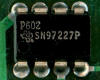 The two calculator chips use two non-overlapping clock signals PHI 1 and PHI 2
with a frequency of up to 250 kHz, to optimize the power budget of the SR-50A an
innovative clock circuitry slows down the clock frequency of the system while
the calculator is just displaying results and scanning the keyboard and not
performing actual calculations. While the original SR-50 used a clock generation
circuitry composed of multiple discrete components, utilizes the SR-50A (Version
1) a SN97227 Clock Generator Chip in a
small 8-pin DIP (Dual In-line Package with a 0.1” / 2.54 mm lead pitch) housing
together with a TP4011A Clock Buffer Chip
in a 14-pin DIP housing to reduce both real estate on the PCB and manufacturing
costs. Please notice the small "190" mark on the TP4011A, obviously a reference
to the TP0190N designation used with the
SR-52.
The two calculator chips use two non-overlapping clock signals PHI 1 and PHI 2
with a frequency of up to 250 kHz, to optimize the power budget of the SR-50A an
innovative clock circuitry slows down the clock frequency of the system while
the calculator is just displaying results and scanning the keyboard and not
performing actual calculations. While the original SR-50 used a clock generation
circuitry composed of multiple discrete components, utilizes the SR-50A (Version
1) a SN97227 Clock Generator Chip in a
small 8-pin DIP (Dual In-line Package with a 0.1” / 2.54 mm lead pitch) housing
together with a TP4011A Clock Buffer Chip
in a 14-pin DIP housing to reduce both real estate on the PCB and manufacturing
costs. Please notice the small "190" mark on the TP4011A, obviously a reference
to the TP0190N designation used with the
SR-52.
![]() While
the display of the
SR-50 is composed of 14 discrete 7-Segment LED modules with an attached
magnifier lens mounted together with the two SN27882 display drivers
on the Keyboard-PCB, uses the SR-50A a small Display Module soldered directly to
the Main-PCB that includes the display drivers.
While
the display of the
SR-50 is composed of 14 discrete 7-Segment LED modules with an attached
magnifier lens mounted together with the two SN27882 display drivers
on the Keyboard-PCB, uses the SR-50A a small Display Module soldered directly to
the Main-PCB that includes the display drivers.
Texas Instruments even considered to extend its Product Portfolio of
Scientific Calculators and developed a product to slot below the SR-50A that was never introduced to the market. Read more about
the rare SR-40 prototype.
The appearance of the SR-50A previews already the design
language of the later
SR-52 Programmable Calculator.
With the introduction of the SR-56 in Spring 1976 the hardware of both the SR-50A and SR-51A was redesigned to accommodate the TMC0501 Arithmetic Chip, one (SR-50A) or two TMC0530 SCOM Chips (SR-51A and SR-56) and none (SR-50A and SR-51A) or one TMC0599 Multi-Register Chip (SR-56). Read more about the revised SR-50A.
If you have additions to the above article please email: joerg@datamath.org.
© Joerg Woerner, December 5, 2001. No reprints without written permission.