DATAMATH CALCULATOR MUSEUM
|
DATAMATH CALCULATOR MUSEUM |
With the original TMS1000 Microcomputer mainly intended for designs using power-hungry LED displays with external display drivers, uses the TMS1070 redesigned output drivers for the 11 R Outputs (Display Scan) and 8 O Outputs (Segments) that can withstand voltages up to -35 Volts and hence allows direct operation of low-voltage Vacuum Fluorescent Displays (VFDs). All other specifications are identical with the earlier (-15 Volts) standard TMS1000 devices.
| Type | Calculator | Application | Comments |
| TMS1071 | TI-2550 II, Homeland 8105, Privileg 861 MD | Basic, Memory | First TMS1070 application |
| TMC1073 | TI-5100, Panasonic JE-2601U, Toshiba BC-1015 | Small Desktop | |
| TMC1079 | Canon MD-8, MD 810 | Basic and Small Desktop Memory, Process |
First Two-Line Calculator |
| TMC1081 | Panasonic JE-1604U, JE-170U | Small Desktop | 16-digit Arithmetic |
| Description | Comments | |
| Architecture | Single-chip Calculator | First Generation Digit Processor |
| Category | Digit Processor | 4-bit Digits |
| Related |
TMS1000 Portfolio TMS1040 |
9 digits, Integrated Pull-downs |
| ROM Size | 8,192 Bits | 1,024 Words * 8 Bits |
| RAM Size | 256 Bits | 4 Registers * 16 Digits |
| Outputs | 11 Digits 8 Segments |
VFD Digit Drivers VFD Segment Drivers |
| Inputs | 4 Keyboard 0 Miscellaneous |
Digit to Keyboard Scan-Matrix |
The Datamath Calculator Museum DCM-50A (Platform) supports the TMS1070 Product Family directly with the TMS1000 Textool Test Socket set to DCM-50A (TMS1000) mode and patching (swapping) of Pin 20 and Pin 21. Both Characterization of TMS1000 Calculator Circuits and Reverse-engineering of TMS1000 Calculator Circuits is supported by the DCM-50A (TMS1000).
| Parameter | Min | Typ | Max | Unit | Comments |
| VSS | 0 | V | |||
| VDD | -14 | -15 | -17.5 | V | 15V Series |
| IDD | 6 | 10 | mA | 300 kHz, -15V | |
| VOUT | -35 | -30 | 0.3 | V | VFD Output Voltage through 100 kOhm Resistors |
| VIN (K1-K8) | -35 | -30 | 0.3 | V | Input Voltage through 100 kOhm Resistors |
| Ext. CK | 100 | 400 | kHz | Level between VSS and VDD | |
| Int. CK | 250 | 300 | 350 | kHz | Rext= 100 kOhm, Cext= 33 pF |
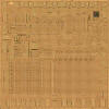
The original TMS1070 was manufactured in a 8 um metal gate PMOS process (metal width = 0.30 mil / 8.0 um, metal spacing = 0.35 mil / 9.0 um, diffusion width = 0.25 mil / 6.0 um, diffusion spacing = 0.35 mil / 9.0 um).
The die size of the TMS1070 is approximately 210 mils * 210 mils / 5.3 mm * 5.3 mm.
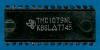
The TMS1070 uses either a 0.6” wide 28-pin DIP (Plastic Dual In-line Package with a 0.1” / 2.54 mm lead pitch)
or a 0.4” wide 28-pin SPDIP (Shrink Plastic Dual In-line Package with a 0.07” / 1.778 mm lead pitch).
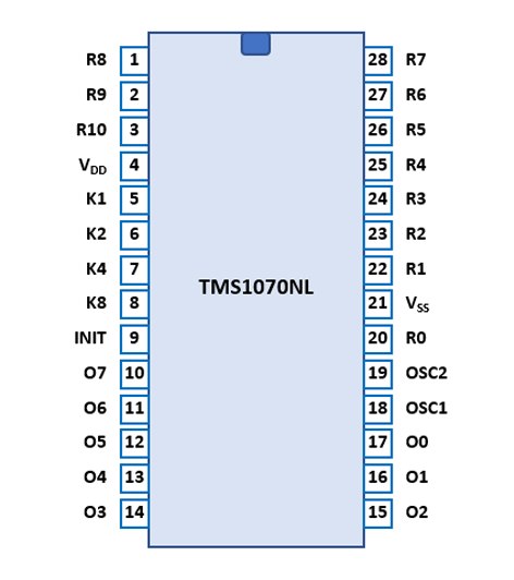
| Pin | IO | Function | Pin | IO | Function |
| 1 | O | R8 Output | 28 | O | R7 Output |
| 2 | O | R9 Output | 27 | O | R6 Output |
| 3 | O | R10 Output | 26 | O | R5 Output |
| 4 | V | Negative Voltage VDD | 25 | O | R4 Output |
| 5 | I | K1 Input | 24 | O | R3 Output |
| 6 | I | K2 Input | 23 | O | R2 Output |
| 7 | I | K4 Input | 22 | O | R1 Output |
| 8 | I | K8 Input | 21 | V | Common Voltage VSS |
| 9 | I | INIT (Reset) | 20 | O | R0 Output |
| 10 | O | O7 Output | 19 | I | OSC2 (Ext. CLK = VSS) |
| 11 | O | O6 Output | 18 | I | OSC1 (Cext, Rext) or Ext |
| 12 | O | O5 Output | 17 | O | O0 Output |
| 13 | O | O4 Output | 16 | O | O1 Output |
| 14 | O | O3 Output | 15 | O | O2 Output |
In a typical calculator application the digits of the display are connected with drivers to the
scanning R Outputs, the segments of the display are connected directly to the O Outputs making use of the
provided 5 to 8 PLA to decode the segments, and the keyboard matrix is connected
between the K Inputs and R Outputs.
Example for the TI-2550 II with TMS1071NL:
| Pin | IO | Function | Pin | IO | Function |
| 1 | O | Digit driver 9 (Sign, M, OF) | 28 | O | Digit driver 8 (MSD) |
| 2 | O | [F - 2] Switch Scanning | 27 | O | Digit driver 7 |
| 3 | O | Not used | 26 | O | Digit driver 6 |
| 4 | V | Negative Voltage VDD | 25 | O | Digit driver 5 |
| 5 | I | K1 Input | 24 | O | Digit driver 4 |
| 6 | I | K2 Input | 23 | O | Digit driver 3 |
| 7 | I | K4 Input | 22 | O | Digit driver 2 |
| 8 | I | K8 Input | 21 | O | Digit driver 1 (LSD) |
| 9 | I | INIT (Reset) | 20 | V | Common Voltage VSS |
| 10 | O | Segment driver DP | 19 | I | OSC2 (Connected to OSC1) |
| 11 | O | Segment driver G | 18 | I | OSC1 (100 pF, 30 kOhm) |
| 12 | O | Segment driver F | 17 | O | Segment driver A |
| 13 | O | Segment driver E | 16 | O | Segment driver B |
| 14 | O | Segment driver D | 15 | O | Segment driver C |
| The Segment drivers A-G and DP (Decimal Point) are connected to the display in the pictured way. | 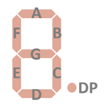 |
Example for the TI-5100 with TMC1073NL:
| Pin | IO | Function | Pin | IO | Function |
| 1 | O | Digit driver 9 | 28 | O | Digit driver 8 |
| 2 | O | Digit driver 10 (MSD) | 27 | O | Digit driver 7 |
| 3 | O | Digit driver 11 (Sign, M, OF, CP) | 26 | O | Digit driver 6 |
| 4 | V | Negative Voltage VDD | 25 | O | Digit driver 5 |
| 5 | I | K1 Input | 24 | O | Digit driver 4 |
| 6 | I | K2 Input | 23 | O | Digit driver 3 |
| 7 | I | K4 Input | 22 | O | Digit driver 2 |
| 8 | I | K8 Input | 21 | O | Digit driver 1 (LSD) |
| 9 | I | INIT (Reset) | 20 | V | Common Voltage VSS |
| 10 | O | Segment driver DP | 19 | I | OSC2 (Connected to OSC1) |
| 11 | O | Segment driver G | 18 | I | OSC1 (100 pF, 30 kOhm) |
| 12 | O | Segment driver F | 17 | O | Segment driver A |
| 13 | O | Segment driver E | 16 | O | Segment driver B |
| 14 | O | Segment driver D | 15 | O | Segment driver C |
| The Segment drivers A-G, DP (Decimal Point) and CP (Comma) are connected to the display in the pictured way. | 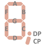 |
The keyboards of calculators based on the TMS1070 Product Family consist of an x/y-matrix connected to the R Outputs R0-R10 and the K Inputs K1, K2, K4, and K8 allowing for a maximum of 44 switches.
Example for the TI-2550 II with TMS1071NL:
| K1 | K2 | K4 | K8 | |
| R0 (D1) | CE | 0 | . | = |
| R1 (D2) | 1 | 2 | 3 | + |
| R2 (D3) | 4 | 5 | 6 | − |
| R3 (D4) | 7 | 8 | 9 | × |
| R4 (D5) | RV | C | % | ÷ |
| R5 (D6) | CM | MR | M− | M+ |
| R6 (D7) | (+/−) | √x | x2 | 1/x |
| R7 (D8) | ||||
| R8 (D9) | ||||
| R9 | ([F - 1]) | [F - 2] | ([F - 4]) | |
| R10 |
Notes: (x) Implemented in TMS1071NL but not available on TI-2550 II. [y z] Sliding Switch Function, y Switch open, z Switch closed
Example for the TI-5100 with TMC1073NL:
| K1 | K2 | K4 | K8 | |
| R0 (D1) | [K - C] | |||
| R1 (D2) | ||||
| R2 (D3) | [F - 2] | |||
| R3 (D4) | ||||
| R4 (D5) | (EX) | (GPM) | (Δ%) | |
| R5 (D6) | C/CE | CM | N | % |
| R6 (D7) | 0 | 1 | 4 | 7 |
| R7 (D8) | 2 | 5 | 8 | |
| R8 (D9) | . | 3 | 6 | 9 |
| R9 (D10) | += | −= | × | |
| R10 (D11) | M+= | M−= | RM | ÷ |
Notes: (x) Implemented in TMC1073NL but not available on TI-5100. [y z] Sliding Switch Function, y Switch open, z Switch closed
Example for the Canon Palmtronic MD-8 with TMC1079NL:
| K1 | K2 | K4 | K8 | |
| R0 (D1) | %± | . | 0 | |
| R1 (D2) | = | RM | 1 | |
| R2 (D3) | ÷ | SC | 2 | |
| R3 (D4) | × | CM | 3 | |
| R4 (D5) | + | √x | 4 | |
| R5 (D6) | − | M+ | 5 | |
| R6 (D7) | RV | 6 | ||
| R7 (D8) | 7 | |||
| R8 (D9) | (C) | 8 | ||
| R9 (D10) | CI/C | 9 | ||
| R10 (D11) | [M-S-P] | [ - AM |
Notes: (x) Implemented in TMC1079NL but not available on Palmtronic MD-8 [y z] Sliding Switch Function, y Switch open, z Switch closed
Example for the Panasonic JE-1604U with TMC1081NL:
| K1 | K2 | K4 | K8 | |
| R0 (D1) | [F - 0] | 0 | . | = |
| R1 (D2) | ([F - 1]) | 1 | n | % |
| R2 (D3) | [F - 2] | 2 | RM | M+ |
| R3 (D4) | [F - 3] | 3 | CM | M− |
| R4 (D5) | [F - 4] | 4 | + | |
| R5 (D6) | ([F - 5]) | 5 | − | |
| R6 (D7) | ([F - 6]) | 6 | × | |
| R7 (D8) | 7 | ÷ | ||
| R8 (D9) | 8 | Δ% | ||
| R9 (D10) | [▼ - 5/4] | 9 | GPM | CE/C |
| R10 (D11) |
Notes: (x) Implemented in TMC1081NL but not available on JE-1604U. [y z] Sliding Switch Function, y Switch open, z Switch closed
Calculators based on the TMS1070 make use of 9-digit or 11-digit low-voltage VFDs (Vacuum Fluorescent Displays).
If you have additions to the above datasheet please email: joerg@datamath.org.
© Sean Riddle and Joerg Woerner, December 9, 2022. No reprints
without written permission.