DATAMATH CALCULATOR MUSEUM
|
|
DATAMATH CALCULATOR MUSEUM |
Characterization of Single-chip Calculator Circuits - TMS0700 Product Family
The DCM-50A Platform supports the Characterization of TMS0700 Devices in its leftmost TMS0100 Textool Test Socket with the voltages VSS set to 7.2V and VGG set to -7.2V, accordingly.
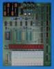
![]() Device-under-Test:
Device-under-Test:
| • Package Markings Top: TMC0138NCΔ,
C 7433 • Package Markings Bottom: JX738 34 • Donor Calculator: Canon Pocketronic II, August 1974 |
Keyboard: The Canon Pocketronic II makes use of a keyboard assembled with individual long-stroke push-button switches arranged in an 11*2 matrix with the rows connected to the D1-D11 Outputs (Display Scan) and the columns connected to the KN (Keyboard Scan Numerical) and KO (Keyboard Scan Operational) Inputs of the TMC0138NC single-chip calculator circuit. The otherwise unused KQ (Keyboard Scan Constant) Input is connected to the RDY Output of the TMS0641 Printer Chip.
Keyboard Matrix of the Canon Pocketronic II:
TMC0738 |
||||
| KN | KO | KP | KQ | |
| D1 | 1 | + | ||
| D2 | 2 | × | ||
| D3 | 3 | ÷ | ||
| D4 | 4 | − | ||
| D5 | 5 | |||
| D6 | 6 | |||
| D7 | 7 | %+/− | ||
| D8 | 8 | = | ||
| D9 | 9 | . | ||
| D10 | 0 | CI | [RDY] | |
| D11 | C | |||
Display: The Canon Pocketronic II is the only known calculator based on the TMS0100 Family using a serial thermal printer to output its results instead of a traditional, digit-scanned display. Texas Instruments developed with the TMS0640 Printer Chip a peripheral device to control the 5x5 heater array of their EPN2500 thermal printhead that connects to a TMS0100 single-chip calculator circuit through a digit-serial BCD Input Port for the numbers and a 6-bit serial Flag Bit Input Signal for symbols and commands.
To allow this unusual approach, the TMS0641 (a mask-programmed version of the TMS0640 Printer Chip for the Canon Pocketronic II) generates the Clock Signal for the TMC0138, a TMS0700 single-chip calculator circuit specifically programmed for the Canon Pocketronic II, and synchronizes its own State Counter and Digit Counter to the TMC0138 by tapping into the S8 signal provided on Segment Output E and the Digit Output D2. Having the TMS0641 operating now perfectly synchronous with the TMC0138, the Printer Chip receives the Numerals from the Calculator Chip in a modified Binary Coded Decimal (BCD) format through the four Segment Outputs SA, SB, SC, and SD. Other symbols like the +, −, and % sign or commands like Print are transferred serially with Segment Output SF as so-called Flag Bits. The Decimal Point information is received directly from the corresponding Segment Output SP while the [C] key is sampled by the TMS0640 Printer Chip during Digit Time D11 on the Keyboard Matrix Input KO. The otherwise unused Keyboard Matrix Input KQ of the Calculator Chip is connected to the Ready Output of the Printer Chip and sampled at Digit Time D10. The TMS0640 Printer Chip uses two separate 13-digit registers to store the received numeric data from the Calculator Chip, the first one acts as an Input Register while the second one is used as Buffer Register during the serial printing of the numbers. A second set of smaller registers is used for the Flag Bits Data, namely a 4-bit register for the various symbols used with the Canon Pocketronic II and a 2-bit register for the print commands.
Printer Layout:
| 4*5 EPN2500 Subarray |
|
|
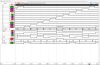
The Output Decoder PLA of the TMC0138NC is programmed to Interface to a TMS0641 Printer Chip with the following Output Assignments:
| TMC0138 Pin | 16 | 17 | 18 | 19 | 20 | 21 | 22 | 23 | 24 |
| TMC0138 Port | SA | SB | SC | SD | SE | SF | SG | SH | SP |
| TMS0641 Pin | A1 | A2 | A4 | A8 | S8 | FLAG | DP |
Printer Fonts:
| Type | Calculator | Number Fonts | Decimal Separator |
Entry Overflow |
Calculating Overflow |
Minus | Symbols |
| TMS0641NC | Canon Pocketronic II |
|
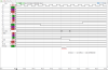
 Scanning: Display and keyboard scanning is performed in D11 → D1 direction at a rate of about
584 Hz with the Digits blanked at State S1 and State S13 but no Segment
blanking on Segment Output Pins SA, SB, SC, SD, SF, SG, and SH. Segment Output
Pin SE is configured to signal State S8 and is hence blanked at S1 → S7 and S9 → S13:
Scanning: Display and keyboard scanning is performed in D11 → D1 direction at a rate of about
584 Hz with the Digits blanked at State S1 and State S13 but no Segment
blanking on Segment Output Pins SA, SB, SC, SD, SF, SG, and SH. Segment Output
Pin SE is configured to signal State S8 and is hence blanked at S1 → S7 and S9 → S13:
|
• State Time = 3 Clocks =
0.012 ms @ CK=250 kHz • Digit Time = 13 States (1 Instruction Cycle) = 0.156 ms @ CK=250 kHz • Scan Time = 11 Digit Times (D1 to D11) = 1.712 ms @ CK=250 kHz |
If you have additions to the above article please email: joerg@datamath.org.
© Joerg Woerner, April 13, 2024. No reprints without written permission.