DATAMATH CALCULATOR MUSEUM
|
DATAMATH CALCULATOR MUSEUM |
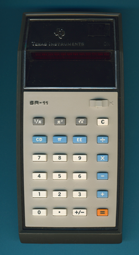
Texas Instruments SR-11 Version 2
| Date of introduction: | September 11, 1973 | Display technology: | LED modules + lens |
| New price: | $119.95 | Display size: | 8 + 2 |
| Size: | 6.3" x 3.1" x
1.5" 158 x 78 x 38 mm3 |
||
| Weight: | 9.2 ounces, 262 grams | Serial No: | SR-11 487223 |
| Batteries: | 3*AA NiCd | Date of manufacture: | wk 38 year 1974 |
| AC-Adapter: | AC9200, AC9130 | Origin of manufacture: | USA |
| Precision: | 8 | Integrated circuits: | TMS0602, 2*SN75493, 2*SN27423 |
| Logic: | Chain | Displays: | DIS115F (12*DISXXX) |
| Memories: | |||
| Program steps: | Courtesy of: | Joerg Woerner | |
| Download manual: | |
![]()
![]() This
SR-11 Version 2 can be distinguished from the original SR-11
Version 1 easily: The white cap covering the sliding switch for the Constant
function was significantly increased to cover the gap in the faceplate of the
calculator.
This
SR-11 Version 2 can be distinguished from the original SR-11
Version 1 easily: The white cap covering the sliding switch for the Constant
function was significantly increased to cover the gap in the faceplate of the
calculator.
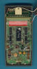
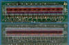
 Dismantling the featured
SR-11 manufactured in
September 1974 by
Texas Instruments in the United States reveals a complex design with three
printed circuit boards (PCBs) for main electronics, display, and keyboard
powered by three AA-sized rechargeable NiCd batteries. The Main-PCB sports not
only five familiar looking Integrated Circuits (ICs) but a myriad of discrete
components in a from the Datamath well known arrangement:
Dismantling the featured
SR-11 manufactured in
September 1974 by
Texas Instruments in the United States reveals a complex design with three
printed circuit boards (PCBs) for main electronics, display, and keyboard
powered by three AA-sized rechargeable NiCd batteries. The Main-PCB sports not
only five familiar looking Integrated Circuits (ICs) but a myriad of discrete
components in a from the Datamath well known arrangement:
|
• Calculating Unit - TMS0602 single-chip calculator circuit • Display Driver - 2*SN75493 Segment Drivers and 2*SN27423 Digit Drivers • Clock signal generation for TMS0602 with discrete components • Power converter with discrete components and transformer • 21-pin connector to the Display-PCB • 15-pin connector to the Keyboard-PCB |
![]() Calculating Unit: The
SR-11 makes use of the TMS0602 single-chip calculator circuit derived from the TMS1802,
better known as first "calculator-on-a-chip" but with a Read-Only program Memory
increased from 320 Words to 384 Words x 11 Bits.
Calculating Unit: The
SR-11 makes use of the TMS0602 single-chip calculator circuit derived from the TMS1802,
better known as first "calculator-on-a-chip" but with a Read-Only program Memory
increased from 320 Words to 384 Words x 11 Bits.
Comparing the feature sets of the TMS0119 (TI-2500), TMS0601 (TI-2550), TMS0120 (SR-10) and TMS0602 (SR-11) shows the limitations of the TMS0100/TMS0600 and explains the move from Texas Instruments towards architectures with scalable ROM configurations like the TMS0200 Building Blocks for Desktop Calculators introduced in 1973 but most important to the TMC0500 Building Blocks for Scientific and Programmable Calculators introduced with the "Slide Rule" calculator SR-50 in January 1974 and leading all the way to the legendary TI Programmable 59 and the amazing SR-60A Prompting Desktop calculator:
| Features/ Device |
[0]...[9] [.] |
[+] [−] [×] [÷] [=] |
[+/−] | [C] [CE] | [CONST] | [F/2/4] | [%] | [Memory] | [EE] | [1/x] | [x2] | [√x] | [PI] | Display Format |
| TMS0119 | * | * | * | * | * | E88888888 | ||||||||
| TMS0601 | * | * | * | * | * | * | * | E88888888 | ||||||
| TMS0120 | * | * | * | * | * | * | * | * | E88888888-88 | |||||
| TMS0602 | * | * | * | * | * | * | * | * | * | * | E88888888-88 |
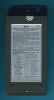
![]() Display: With the TMS0100
and its successor TMS0600 originally developed for portable and desktop
calculators supporting either an 8-digit or 10-digit output with a leading negative
sign/overflow indicator, these chips consequently support only 11 digit outputs
for the display but the SR-11 obviously uses a 12-digit
display for:
Display: With the TMS0100
and its successor TMS0600 originally developed for portable and desktop
calculators supporting either an 8-digit or 10-digit output with a leading negative
sign/overflow indicator, these chips consequently support only 11 digit outputs
for the display but the SR-11 obviously uses a 12-digit
display for:
|
• 1: Overflow indicator, negative sign Mantissa • 2-9: 8-digit Mantissa • 10: Negative sign Exponent • 11-12: 2-digit Mantissa |
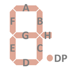
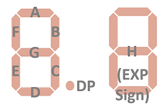 Reverse-engineering
the SR-11 schematics reveals a simple trick used by Texas Instruments to control
its 12-digit display with only 11 digit outputs of the TMS0602 and known already
from the second version of the SR-10: The unused "H"
segment available on the TMS0602 was repurposed for the minus sign of the
Exponent in the pictured (pictures on the left) way. Every time the "H" segment
output of the TMS0602 is activated, some additional circuitry on the PCB will
enable both the digit driver for the negative sign of the Exponent and the
segment driver for the "G" segment of Digit 3 (counted from right to
left) of the DIS115F Twelve-Digit display
module while the "G" segments of all other digits are activated by the "G"
segment output. Hence you'll find 21 connections between the Main-PCB and the
DIS115 Display-PCB:
Reverse-engineering
the SR-11 schematics reveals a simple trick used by Texas Instruments to control
its 12-digit display with only 11 digit outputs of the TMS0602 and known already
from the second version of the SR-10: The unused "H"
segment available on the TMS0602 was repurposed for the minus sign of the
Exponent in the pictured (pictures on the left) way. Every time the "H" segment
output of the TMS0602 is activated, some additional circuitry on the PCB will
enable both the digit driver for the negative sign of the Exponent and the
segment driver for the "G" segment of Digit 3 (counted from right to
left) of the DIS115F Twelve-Digit display
module while the "G" segments of all other digits are activated by the "G"
segment output. Hence you'll find 21 connections between the Main-PCB and the
DIS115 Display-PCB:
|
• 12 connections for Digit 1 to Digit 12 • 1 connection for Segments G of Digit 3 • 1 connection for Segments G of Digit 1, Digit 2 and Digit 4 to Digit 12 • 6 connections for Segments A, B, C, D, E, and F of Digit 1 to Digit 12 • 1 connection for Decimal Point of Digit 1 to Digit 12 |
The featured SR-11 manufactured in September 1974 uses a DIS115F Twelve-Digit display module with 12 individual DISXXX Seven-Segment displays and an integrated magnifying lens.
![]()
![]() Display Driver: The Main-PCB of the featured
SR-11 manufactured in September 1974 makes use of a total of four Display Drivers. The two
SN75493 Segment Drivers for four segments, each and the two
SN27423 (SN75494) Digit Drivers for six digits, each are improvements of the original
SN75491/SN75492
chips introduced with the TMS1802 but allow for operation at lower voltages. We
do not recognize the manufacturer of the SN27423 chips due to the missing
company logos.
Display Driver: The Main-PCB of the featured
SR-11 manufactured in September 1974 makes use of a total of four Display Drivers. The two
SN75493 Segment Drivers for four segments, each and the two
SN27423 (SN75494) Digit Drivers for six digits, each are improvements of the original
SN75491/SN75492
chips introduced with the TMS1802 but allow for operation at lower voltages. We
do not recognize the manufacturer of the SN27423 chips due to the missing
company logos.
Clock: While the nominal clock frequency of the TMS0600 single-chip calculator circuit is specified with 250 kHz, uses the SR-11 a slower pace to reduce overall power consumption of the product slightly. The astable multivibrator using two discrete transistors operates at a frequency between 150 kHz and 250 kHz, we observed with the featured SR-11 manufactured in September 1974 a clock frequency of 185 kHz.
Texas Instruments introduced in August 1973 with the TI-2500 Version 3 the approach of a dynamic switching of the clock frequency for the TMS0100 single-chip calculator circuit to conserve power between calculations. The astable multivibrator idles at a frequency of around 50 kHz but increases with the detection of a depressed keybutton for a short time to about 200 kHz to reduce execution time of the operations. Two diodes are connected between the keymatrix inputs KN (numbers) and KO (operations) and the oscillator to catch every entry of a number or function keys for a impressive reduction of power consumption.
Power Supply: The SR-11 is powered by three AA-sized rechargeable NiCd batteries resulting in a typical voltage between 3.0 V (completely depleted cells) and 4.5 V (while charging full cells). The Main-PCB hosts a power converter circuit centered around an astable multivibrator, step-up transformer and various diodes and capacitors to generate the supply voltages for the TMS0602 chip and the clock oscillator. We observed in the featured SR-11 manufactured in September 1974 rather high output voltages of VSS = 8.4 V and VGG = -8.9 V for the electronics.
Battery Saver Circuit: To save battery power the LED display turns off automatically between 15 and 60 seconds after the last keyboard entry, except for the first digit (Digit D3 of TMS0602, LSD of Mantissa). If the display turns off while entering a problem, the display turns on automatically with the first keyboard entry. Depressing the [=] key brings back the last calculated display. Three diodes are connected between the keymatrix inputs KN (numbers), KO (operations, [pi]) and KP ([1/x], [x2] and [sqr X]) and a simple monoflop to catch every entry of a number or function keys to keep the Digit Drivers enabled. If the monoflop time expires, the Digit Drivers sans Digit 3 are disabled for an impressive reduction of power consumption:
| Mode | Display | Current VBAT = 4.5 V |
Clock Frequency |
| Calculating | 0 | 59 mA | 188 kHz |
| Power Save | 0 | 60 mA | 188 kHz |
| Calculating | E88888888-88 | 135 mA | 188 kHz |
| Power Save | 8 | 71 mA | 188 kHz |
Keyboard: The Klixon™ type keyboard uses much smaller keys than the SR-10 calculator in the same extreme wedge-style of the housing that was adopted for the scientific desktop calculators SR-20 and SR-22, too. The last portable scientific calculator with this wedge-design was introduced in October 1974 with the SR-16.
 The appearance of the SR-11 changed during the life cycle
(around May 1974) of
the calculator slightly and together with a change of the twelve individual
Seven-Segment displays used for the DIS115 display module, we differentiate between
three different SR-11
Versions manufactured in the United States between September 1973 and October 1975:
The appearance of the SR-11 changed during the life cycle
(around May 1974) of
the calculator slightly and together with a change of the twelve individual
Seven-Segment displays used for the DIS115 display module, we differentiate between
three different SR-11
Versions manufactured in the United States between September 1973 and October 1975:
| Version | Display Type |
Displays for DIS115 |
Constant Switch |
| SR-11 V1D1 | single modules with lens |
DIS279 | Small Cap |
| SR-11 V1D2 | single modules with lens |
DISXXX | Small Cap |
| SR-11 V2D2 | single modules with lens |
DISXXX | Large Cap |
Here at the Datamath Calculator Museum we classify the featured SR-11 as Display Type 2 and Large Cap for Constant Switch.
The SR-11 was not only manufactured in the United States, but in Italy and Spain, too.
It took 12 years and a similar scientific calculator with just the [1/x], [x2], [√x] and [PI] keys appeared, don't miss the unusual TI-18 SLR.
![]() Press the X-RAY button and view the
internals of a SR-11 calculator.
Press the X-RAY button and view the
internals of a SR-11 calculator.
(Pictures provided by Edward Soudentas)


 Update (December 2024):
On our quest to complete the
Characterization of Single-Chip Calculator Circuits
of the TMS0600 Product Family, we decided here at
the Datamath Calculator Museum to give the SR-11 calculator with its
TMS0602 chip a "Teardown Treatment" and share our findings accordingly.
Our donor calculator with serial number #604261 and
manufactured in November 1974 matches the featured SR-11 (Version 2) but uses a
slightly different
Display DIS005G instead the DIS115F. In a first step did we observe with a Mixed Signal Oscilloscope
(MSO) the signals at the TMS0602 chip to verify its pin-out before disassembling
the calculator completely to analyze its printed circuit board (PCB) wiring.
Update (December 2024):
On our quest to complete the
Characterization of Single-Chip Calculator Circuits
of the TMS0600 Product Family, we decided here at
the Datamath Calculator Museum to give the SR-11 calculator with its
TMS0602 chip a "Teardown Treatment" and share our findings accordingly.
Our donor calculator with serial number #604261 and
manufactured in November 1974 matches the featured SR-11 (Version 2) but uses a
slightly different
Display DIS005G instead the DIS115F. In a first step did we observe with a Mixed Signal Oscilloscope
(MSO) the signals at the TMS0602 chip to verify its pin-out before disassembling
the calculator completely to analyze its printed circuit board (PCB) wiring.
 Confirming the pin-out of the calculator chip and reverse-engineering the
keyboard matrix, we were able to fully operate the TMS0602 with our DCM-50A
Platform and not only measure precisely the timing of its Display and Keyboard
interface but digging deeper into the algorithm embedded in its firmware. Analyzing the Feature Sets and
Calculator Logic Implementations
of the six known members of the (not so successful) TMS0600 Product Family, we
can summarize: Too Little, Too Late. When Texas Instruments introduced the
TMS0600 early in 1974, with custom-specific designs not available before Summer
1974, the market of pocket calculators diverted into two directions:
Confirming the pin-out of the calculator chip and reverse-engineering the
keyboard matrix, we were able to fully operate the TMS0602 with our DCM-50A
Platform and not only measure precisely the timing of its Display and Keyboard
interface but digging deeper into the algorithm embedded in its firmware. Analyzing the Feature Sets and
Calculator Logic Implementations
of the six known members of the (not so successful) TMS0600 Product Family, we
can summarize: Too Little, Too Late. When Texas Instruments introduced the
TMS0600 early in 1974, with custom-specific designs not available before Summer
1974, the market of pocket calculators diverted into two directions:
| • Enhanced Feature Set, Low Cost • Standard Feature Set, Lowest Cost |
With the rather limited program memory (384 Words * 11 Bits) and small data memory (3 * 13 Digits Registers), the functionality of all six known TMS0600 designs wasn't competitive and the restriction to LED displays with external digit drivers and missing an internal clock oscillator didn't help with the manufacturing costs of an electronic calculator.
If you have additions to the above article please email: joerg@datamath.org.
© Joerg Woerner, September 23, 2003. No reprints without written permission.