DATAMATH CALCULATOR MUSEUM
|
DATAMATH CALCULATOR MUSEUM |
Mostek Corporation introduced in March 1973 with the MK5020 and MK5021 their first "true" single-chip calculators following the MK6010, MK6010L, and MK5010 devices. The MK5020 Product Family is a programmable single-chip calculator which is both pin compatible (sans Pin 14) and function compatible with the Texas Instruments one-chip calculator circuit TMS1802 and the TMS0100 Family. Improved features are available from the MK5020 Product Family, including:
|
• Lower power
dissipation • Single supply operation • Broader supply voltage operating range • Internal clock oscillator • More extensive programmability |
 The first four functions
above were made possible through the use of Mostek's ion-implantation,
depletion-mode load, P-channel MOS process. These features make the MK5020
Product Family
ideal for battery operated hand-held calculators where battery life and
calculator compactness are prime considerations. The more extensive
programmability due to a larger Read-Only program Memory (ROM, 384 Words x 11
Bits vs. 320 Words x 11 Bits) of the MK5020 Product Family allows implementation of complex special
functions through custom programming.
The first four functions
above were made possible through the use of Mostek's ion-implantation,
depletion-mode load, P-channel MOS process. These features make the MK5020
Product Family
ideal for battery operated hand-held calculators where battery life and
calculator compactness are prime considerations. The more extensive
programmability due to a larger Read-Only program Memory (ROM, 384 Words x 11
Bits vs. 320 Words x 11 Bits) of the MK5020 Product Family allows implementation of complex special
functions through custom programming.
Due to a flexible design concept with both programmable PLA and ROM techniques a lot of design variations appeared with the expanded MK5020 Product Family (1974). These include different types of the key-matrix, 8 or 10 Digits of 7- or 8-segmented outputs. The two letters behind the product designation define the ROM-code (A,B,C...) and package (P for ceramic housing).
A typical calculator built around the MK5020 Product Family performs the four basic functions +, −, ×, and ÷ with either Constant or Chain operation. Additional both a % and √x function are available with the MK5020 and MK5021. The calculations are done on a floating decimal-point operation but the display of the results could be selected between the floating-point or a fixed-point format. The keyboard scanning, debouncing and encoding in performed inside the chip. The display outputs are fully decoded with a leading zero suppression and multiplexed.
QUICK-LINK to Mostek Calculator Integrated Circuits.
| Type | Calculators | Keyboard | Constant A/S/M/D |
Digits | Fixed DP | Rounding | Special Functions |
Seg./Dig. Blanking |
(6,7,9) Font |
Seg. H | Entry Overflow |
Calculating Overflow |
Memory Indicator |
| MK5020A | Corvus 0310, Heathkit IC-2006 | [+=][−=] [+][−][=] |
1/1/1/2 | 8 | F, 0-7 | 3-POS | [%] [√x] | S1, S13 S1, S13 |
n.a. | ||||
| MK5020B | Aristo M64, Privileg 01466 | [+=][−=] [+][−][=] |
1/1/1/2 | 8 | F, 0-7 | 3-POS | [%] [√x] | S1, S13 S1, S13 |
n.a. | ||||
| MK5021C | Interton VIP 10 | [+=][−=] [+][−][=] |
1/1/1/2 | 10 | F, 0-9 | 3-POS | [%] [√x] Floating sign |
S1, S13 S1, S13 |
n.a. | ||||
| TMS0105 Reference | Canon L800 | [+=][−=] | -/-/1/2 | 8 | F, 0-7 | 5/4 | NONE S1, S13 |
n.a. | |||||
| TMS0106 Reference | TI-3500 | [+=][−=] | -/-/1/2 | 10 | F, 0-9 | 3-POS | S1, S13 S1, S13 |
n.a. |
The Datamath Calculator Museum DCM-50A (Platform) supports the MK5020 Product Family directly with the TMS1000 Textool Test Socket set to DCM-50A (TMS1000) mode and patching (swapping) most of the pins. One additional patch wire is needed to connect the Segment H output not available on the TMS1000 Socket but on the TMS0100 Socket. Both Characterization of TMS1000 Calculator Circuits and Reverse-engineering of TMS1000 Calculator Circuits is supported by the DCM-50A (TMS1000), an additional "pull-down" resistor is necessary for the Clock Output pin of the MK5020 chip. The voltages VSS and VDD/VGG are set to 9.5V and -5.5V, respectively. Alternatively the MK5020 chip can be placed in the TMS0100 Textool Test Socket set to DCM-50A (TMS0100) mode and Pin 14 isolated.
| Item | Min | Typ | Max | Unit | Comments |
| VSS | 0 | V | |||
| VGG | -11.0 | -14.4 | -17.0 | V | Datasheet (C) 1973 |
| IGG | 6.5 | mA | Datasheet (C) 1973 | ||
| CK | 182 | kHz | 200 kOhm and 36 pF |
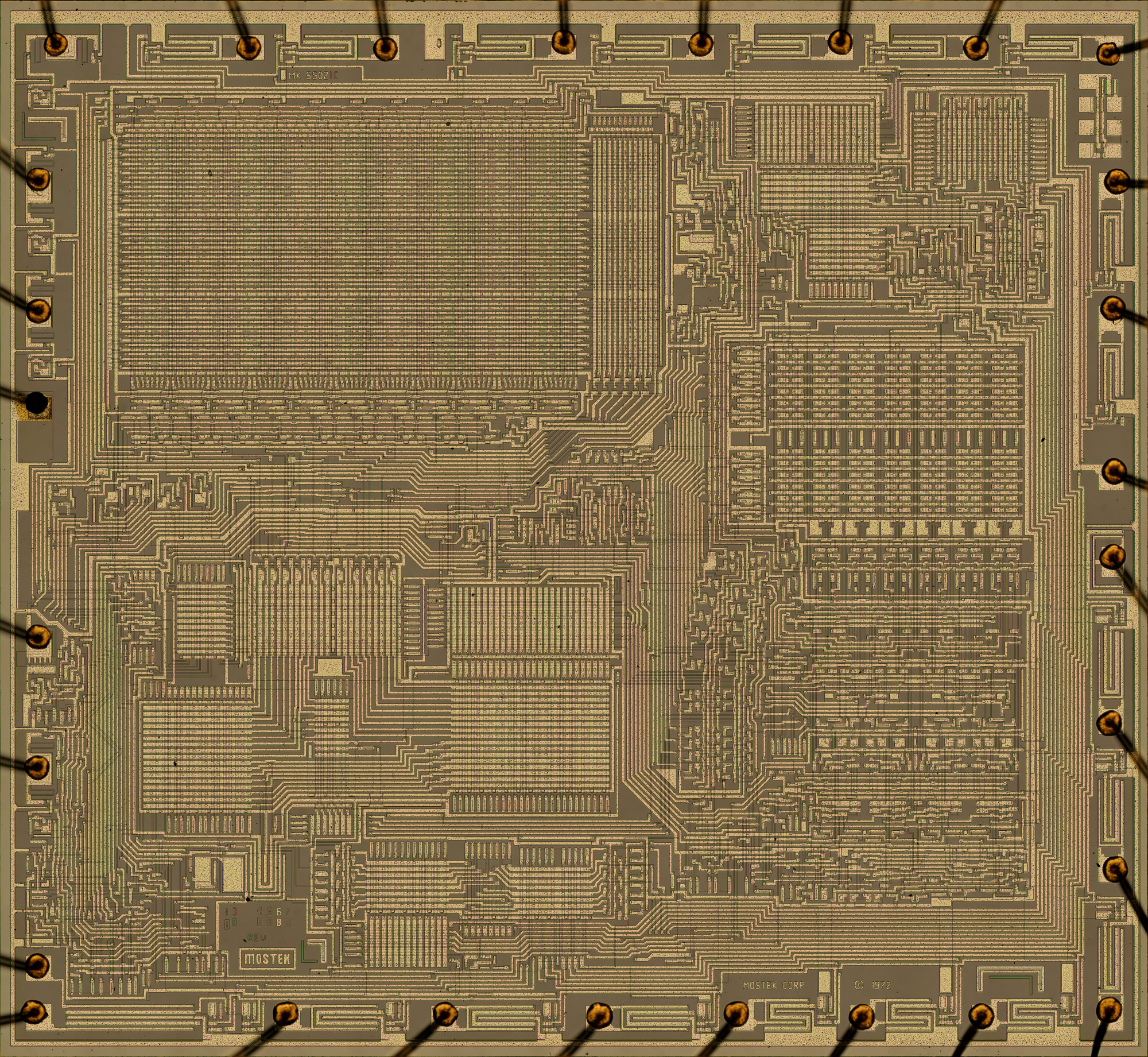
The MK5020 uses a 0.6” wide 28-pin CDIP (Ceramic Dual In-line Package with a 0.1” / 2.54 mm lead pitch).
The MK5020 was manufactured in a 10 um metal gate PMOS process (metal width = 0.40 mil / 10.0 um, metal spacing = 0.30 mil / 7.5 um, diffusion width = 0.30 mil / 7.5 um, diffusion spacing = 0.25 mil / 6.0 um).
The die size of the MK5020 is approximately 195 mils * 180 mils / 5.0 mm * 4.6 mm.
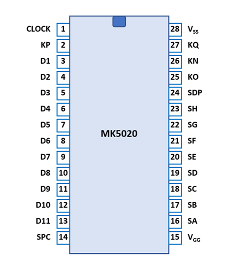
| Pin | IO | Function | Pin | IO | Function |
| 1 | I | Clock Input | 28 | V | Common Voltage |
| 2 | I | Keymatrix input P | 27 | I | Keymatrix input Q |
| 3 | O | Digit driver 1 (LSD) | 26 | I | Keymatrix input N |
| 4 | O | Digit driver 2 | 25 | I | Keymatrix input O |
| 5 | O | Digit driver 3 | 24 | O | Segment driver DP |
| 6 | O | Digit driver 4 | 23 | O | Segment driver H |
| 7 | O | Digit driver 5 | 22 | O | Segment driver G |
| 8 | O | Digit driver 6 | 21 | O | Segment driver F |
| 9 | O | Digit driver 7 | 20 | O | Segment driver E |
| 10 | O | Digit driver 8 (MSD8) | 19 | O | Segment driver D |
| 11 | O | Digit driver 9 | 18 | O | Segment driver C |
| 12 | O | Digit driver 10 (MSD10) | 17 | O | Segment driver B |
| 13 | O | Digit driver 11 (OVER) | 16 | O | Segment driver A |
| 14 | O | Clock Output | 15 | V | Negative Voltage VGG |
| The Segment drivers A-H and the Decimal point are connected to a display in the pictured way. | 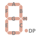 |
The keyboards of all calculators based on the MK5020 Product Family consists of a x/y-matrix connected to the digit driver outputs D1-D11 and the keymatrix inputs KN and KO. In the fixed-point output format mode the position of the decimal point is selected with the KP input. The Constant/Chain switch is connected between D10-KQ. The √x function requires one additional diode between D4-KQ and two diodes between its switch and D6-KO and D7-KO.
MK5020 |
MK5021 |
||||||||
| KN | KO | KP | KQ | KN | KO | KP | KQ | ||
| D1 | 1 | + | DP1 | D1 | 1 | + | DP1 | ||
| D2 | 2 | × | DP2 | D2 | 2 | × | DP2 | ||
| D3 | 3 | ÷ | DP3 | D3 | 3 | ÷ | DP3 | ||
| D4 | 4 | − | DP4 | (√x) | D4 | 4 | − | DP4 | (√x) |
| D5 | 5 | += | DP5 | D5 | 5 | += | DP5 | ||
| D6 | 6 | −= (*) | DP6 | D6 | 6 | −= (*) | DP6 | ||
| D7 | 7 | +/− (*) | DP7 | RND Up | D7 | 7 | +/− (*) | DP7 | RND Up |
| D8 | 8 | = | D8 | 8 | = | DP8 | |||
| D9 | 9 | . | RND Down | D9 | 9 | . | DP9 | RND Down | |
| D10 | 0 | CE | DP0 | K | D10 | 0 | CE | DP0 | K |
| D11 | % | C | D11 | % | C | ||||
Notes: (*) √x function activated with [−=] and [+/−] keys pressed simultaneously when D4-KQ connected with diode
Calculators based on the MK5020 use normally LED displays. Texas Instruments introduced together with their calculator chips two pre-configured LED-modules (DIS40, DIS95) based on the TIL360 arrays, the corresponding segment drivers (SN75491) and digit drivers (SN75492). Many designs make use of these or similar components.
If you have additions to the above datasheet please email: joerg@datamath.org.
© Joerg Woerner, February 02, 2001. No reprints
without written permission.