DATAMATH CALCULATOR MUSEUM
|
|
DATAMATH CALCULATOR MUSEUM |
Characterization of Single-chip Calculator Circuits - TMS0970 Product Family
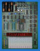
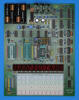
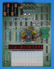
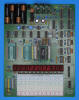
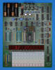
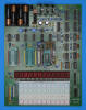
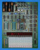
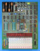
The DCM-50A Platform supports the Characterization of 28-pin TMS0970 and TMC0900 Devices in its rightmost TMS1000 Textool Test Socket using an additional TMS0900 Adapter and the voltages VSS set to 9.5V and VDD/VGG set to -5.5V, accordingly. The TMS0900 Adapter supports a maximum of 9 digit drivers but allows to jumper them to any set of the maximum of 11 digit drivers of the TMS0970 silicon chip. Pleas notice that layout of the TMS0900 Adapter maps the nine Digit Outputs D9 (MSD) to D1 (LSD) of the device under test to the corresponding R10 to R2 Outputs of the TMS1000 socket, hence creating an MSD-aligned 7-Segment Display on the DCM-50A Platform.
![]() Device-under-Test:
Device-under-Test:
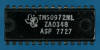
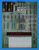
| • Package Markings Top:
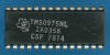
TMS0972NL, ZA0348, ASP 7628 • Package Markings Bottom: ⚫JP0972AS, SINGAPORE • Donor Product: TI-1200, October 1976 |
Keyboard: The TI-1200 makes use of a keyboard with snap-action dome switches arranged in an 5*4 matrix with the rows connected to the scanning O1-O5 Segment Outputs (Display Scan) and the columns connected to the K1-K8 Inputs (Keyboard Scan) of the TMS0972NL single-chip calculator circuit. Please notice that the otherwise identical TI-1250 uses a 6*4 keyboard matrix with the O7 Segment Output scanning the extra row of [MC], [MR], [M−], and [M+] keys. Some TI-1200 even use the 6*4 keyboard and just hide the extra functionality including the [+/−] key with the face plate.
Keyboard Matrix of the TI-1200:
| K1 | K2 | K4 | K8 | |
| O7 (Seg. DP) | (MC) | (MR) | (M−) | (M+) |
| O6 (Seg. G) | ||||
| O5 (Seg. F) | C | (+/−) | % | ÷ |
| O4 (Seg. E) | 7 | 8 | 9 | × |
| O3 (Seg. D) | 4 | 5 | 6 | − |
| O2 (Seg. C) | 1 | 2 | 3 | + |
| O1 (Seg. B) | CE | 0 | . | = |
| O0 (Seg. A) |
![]() Display: The
TI-1200 makes use of a DIS233G Nine-Digit Calculator Numeric Seven-Segment LED
Display module without the leading digit populated directly connected to the
corresponding Digit Output pins R0 to R7 (LSD to sign/MSD) and Segment Output pins O0 to O7
(SA to SDP).
Display: The
TI-1200 makes use of a DIS233G Nine-Digit Calculator Numeric Seven-Segment LED
Display module without the leading digit populated directly connected to the
corresponding Digit Output pins R0 to R7 (LSD to sign/MSD) and Segment Output pins O0 to O7
(SA to SDP).
Display Layout:
| Texas Instruments DIS-233G (8) |
|
|
The Output Decoder PLA of the TMS0972NL (DIP-28) is programmed for 7-Segment displays with the following Output Assignments:
| TMS0972 Pin | 17 | 16 | 15 | 14 | 13 | 12 | 11 | 10 |
| TMS0972 Port | O0 | O1 | O2 | O3 | O4 | O5 | O6 | O7 |
| Segment | A | B | C | D | E | F | G | DP |
| The Segment drivers A-G and DP (Decimal Point) are connected to the Seven Segment display in the pictured way. | 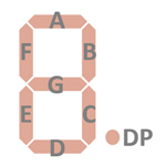 |
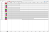
Display Fonts:
| Type | Calculator | Number Fonts | Decimal Separator |
Thousands Separator |
Entry Overflow |
Calculating Overflow |
Minus | (Memory Indicator) |
| TMS0972NL | TI-1200 | n.a. | FLASHING |
|
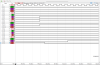
 Overflow conditions of the TI-1200 like dividing a number by
zero
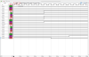
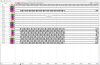
are resulting in a "Flashing" display on the calculator. We analyzed the implementation of the
"Flashing" display with a Digilent Digital Discovery Logic Analyzer connected to
a TMS0972NL operated in the DCM-50A Platform while
performing certain math calculations in parallel with an actual TI-1200.
Overflow conditions of the TI-1200 like dividing a number by
zero
are resulting in a "Flashing" display on the calculator. We analyzed the implementation of the
"Flashing" display with a Digilent Digital Discovery Logic Analyzer connected to
a TMS0972NL operated in the DCM-50A Platform while
performing certain math calculations in parallel with an actual TI-1200.
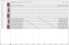
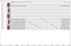
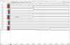
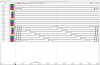
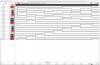
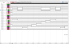
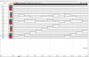
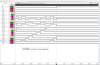
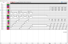
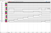
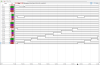
The TMS0972 alternates
in this condition between two completely different Display Scanning Cycles,
resulting in a Flash-Frequency of about 5 Hz:
| • Display on - 16 normal
cycles O7 → O0 (around 75 ms) • Display off - 2 slow-motion cycles in different order (around 125 ms) |
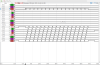
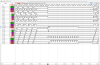
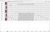
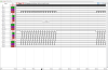
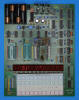
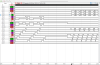
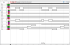
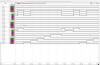
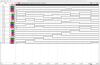 Scanning: Display and keyboard scanning is performed in
O7 → O0 direction at a rate of about
220 Hz with the O0 State stretched slightly:
Scanning: Display and keyboard scanning is performed in
O7 → O0 direction at a rate of about
220 Hz with the O0 State stretched slightly:
|
• Instruction Cycle Time
(ICT) = 6 Clocks = 0.02 ms @ CK=300 kHz • Active Digit Time O6 → O1 = 189 ICT = 3.78 ms • Active Digit Time O0 = 34 ICT = 0.68 ms • Display Cycle Time = 308 ICT = 4.46 ms |
Please notice that the TMS0972 is outputting an active Memory Indicator despite the left most digit of the display not populated.
 Device-under-Test:
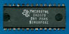
| • Package Markings Top:
TMS0972NL, ZA0348, ASP 7727 • Package Markings Bottom: ⚫DP0972AS, SINGAPORE • Donor Product: TI-1250, August 1977 |
Keyboard: The TI-1250 makes use of a keyboard with snap-action dome switches arranged in an 6*4 matrix with the rows connected to the scanning O1-O5, O7 Segment Outputs (Display Scan) and the columns connected to the K1-K8 Inputs (Keyboard Scan) of the TMS0972NL single-chip calculator circuit.
Keyboard Matrix of the TI-1250:
| K1 | K2 | K4 | K8 | |
| O7 (Seg. DP) | MC | MR | M− | M+ |
| O6 (Seg. G) | ||||
| O5 (Seg. F) | C | +/− | % | ÷ |
| O4 (Seg. E) | 7 | 8 | 9 | × |
| O3 (Seg. D) | 4 | 5 | 6 | − |
| O2 (Seg. C) | 1 | 2 | 3 | + |
| O1 (Seg. B) | CE | 0 | . | = |
| O0 (Seg. A) |
![]() Display: The
TI-1250 makes use of a DIS233G Nine-Digit Calculator Numeric Seven-Segment LED
Display module without the leading digit populated directly connected to the
corresponding Digit Output pins R0 to R7 (LSD to sign/MSD) and Segment Output pins O0 to O7
(SA to SDP).
Display: The
TI-1250 makes use of a DIS233G Nine-Digit Calculator Numeric Seven-Segment LED
Display module without the leading digit populated directly connected to the
corresponding Digit Output pins R0 to R7 (LSD to sign/MSD) and Segment Output pins O0 to O7
(SA to SDP).
Display Layout:
| Texas Instruments DIS-233G (8) |
|
|
The Output Decoder PLA of the TMS0972NL (SPDIP-28) is programmed for 7-Segment displays with the following Output Assignments:
| TMS0972 Pin | 18 | 17 | 16 | 15 | 13 | 12 | 11 | 10 |
| TMS0972 Port | O0 | O1 | O2 | O3 | O4 | O5 | O6 | O7 |
| Segment | A | B | C | D | E | F | G | DP |
| The Segment drivers A-G and DP (Decimal Point) are connected to the Seven Segment display in the pictured way. | |
Display Fonts:
| Type | Calculator | Number Fonts | Decimal Separator |
Thousands Separator |
Entry Overflow |
Calculating Overflow |
Minus | Memory Indicator |
| TMS0972NL | TI-1250 | n.a. | FLASHING |
|
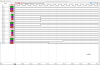
 Overflow conditions of the TI-1200 like dividing a number by
zero
or changing the sign of a number with 8 digits before the decimal point are resulting in a "Flashing" display on the calculator. We analyzed the implementation of the
"Flashing" display with a Digilent Digital Discovery Logic Analyzer connected to
a TMS0972NL operated in the DCM-50A Platform while
performing certain math calculations in parallel with an actual TI-1250.
Overflow conditions of the TI-1200 like dividing a number by
zero
or changing the sign of a number with 8 digits before the decimal point are resulting in a "Flashing" display on the calculator. We analyzed the implementation of the
"Flashing" display with a Digilent Digital Discovery Logic Analyzer connected to
a TMS0972NL operated in the DCM-50A Platform while
performing certain math calculations in parallel with an actual TI-1250.
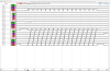
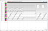
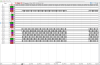
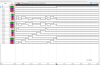
The TMS0972 alternates
in this condition between two completely different Display Scanning Cycles,
resulting in a Flash-Frequency of about 5 Hz:
| • Display on - 16 normal
cycles O7 → O0 (around 75 ms) • Display off - 2 slow-motion cycles in different order (around 125 ms) |
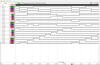
 Scanning: Display and keyboard scanning is performed in
O7 → O0 direction at a rate of about
220 Hz with the O0 State stretched slightly:
Scanning: Display and keyboard scanning is performed in
O7 → O0 direction at a rate of about
220 Hz with the O0 State stretched slightly:
|
• Instruction Cycle Time
(ICT) = 6 Clocks = 0.02 ms @ CK=300 kHz • Active Digit Time O6 → O1 = 189 ICT = 3.78 ms • Active Digit Time O0 = 34 ICT = 0.68 ms • Display Cycle Time = 308 ICT = 4.46 ms |
Please notice that the TMS0972 is outputting an active Memory Indicator despite the left most digit of the display not populated.
![]() Device-under-Test:
Device-under-Test:
| • Package Markings Top:
B733-2 ML980, BP 7706 • Package Markings Bottom: ⚫DP0973B, SINGAPORE • Donor Product: Radio Scanner Bearcat 210, August 1977 |
Keyboard: The Electra Bearcat 210 (BC-210) Radio Scanner makes use of a keyboard with twenty push-button switches arranged in an 8*3 matrix with the rows connected to the scanning O0-O7 Segment Outputs (Display Scan) and the columns connected to the K2-K8 Inputs (Keyboard Scan) of the TMS0973NL single-chip calculator circuit. The K1 Input is used during the R10 Digit Time together with the Segment Outputs to communicate with the Synthesizer chip through its shift register.
Keyboard Matrix of the Electra Bearcat 210:
| K1 | K2 | K4 | K8 | |
| O7 (Seg. DP) | 7 | . | ||
| O6 (Seg. G) | 6 | 9 | ||
| O5 (Seg. F) | 5 | 8 | ||
| O4 (Seg. E) | 4 | SCAN | ||
| O3 (Seg. D) | 3 | E | UPPER | |
| O2 (Seg. C) | 2 | DELAY | LOWER | |
| O1 (Seg. B) | 1 | LOCKOUT | START | |
| O0 (Seg. A) | 0 | MANUAL | HOLD |
Display: The Electra Bearcat 210 makes use makes use ten discrete Common-Cathode Seven-Segment LED Displays soldered onto a small printed circuit board (PCB) and controlled with 10 additional driver transistors for the cathodes from the corresponding Output pins R0 to R9 and 8 additional driver transistors for the segments SA to SDP from the Output pins O0 to O7.
Display Layout:
| Discrete Seven-Segment LED Displays |
|
|
The Output Decoder PLA of the TMS0973NL is programmed for 7-Segment displays with the following Output Assignments:
| TMS0973 Pin | 18 | 17 | 16 | 15 | 14 | 13 | 12 | 11 |
| TMS0973 Port | O0 | O1 | O2 | O3 | O4 | O5 | O6 | O7 |
| Segment | A | B | C | D | E | F | G | DP |
| The Segment drivers A-G and DP (Decimal Point) are connected to the Seven Segment display in the pictured way. | |
Display Fonts:
| Type | Product | Number Fonts | Decimal Separator |
Scan Delay |
| TMS0973NL | BC-210 |
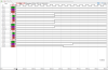
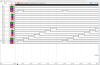
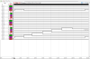
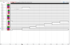
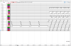
 Scanning: Display and keyboard scanning is performed in
O7 → O0 direction at a rate of about
160 Hz. During communication with the Synthesizer chip of the BC-210 both
display and keyboard scanning is paused for about 60 ms and the R10 Output
activated. The O0 to O7 Outputs are used during R10 Digit Time together with the
K1 Input to exchange data with the shift register of the Synthesizer chip.
During normal display scanning both O7 and O0 States are stretched slightly:
Scanning: Display and keyboard scanning is performed in
O7 → O0 direction at a rate of about
160 Hz. During communication with the Synthesizer chip of the BC-210 both
display and keyboard scanning is paused for about 60 ms and the R10 Output
activated. The O0 to O7 Outputs are used during R10 Digit Time together with the
K1 Input to exchange data with the shift register of the Synthesizer chip.
During normal display scanning both O7 and O0 States are stretched slightly:
|
• Instruction Cycle Time
(ICT) = 6 Clocks = 0.02 ms @ CK=300 kHz • Active Digit Time O7 = 44 ICT = 0.88 ms • Active Digit Time O6 → O1 = 210 ICT = 4.20 ms • Active Digit Time O0 = 54 ICT = 1.08 ms • Display Cycle Time = 308 ICT = 6.16 ms |
![]() Device-under-Test:
Device-under-Test:
| • Package Markings Top:
TMS0974NL, ZA0355, AP 7624 • Package Markings Bottom: ⚫DP0974A, SINGAPORE • Donor Product: TI-1270, July 1976 |
Keyboard: The TI-1270 makes use of a keyboard with snap-action dome switches arranged in an 6*4 matrix with the rows connected to the scanning O1-O5 and O7 Segment Outputs (Display Scan) and the columns connected to the K1-K8 Inputs (Keyboard Scan) of the TMS0974NL single-chip calculator circuit.
Keyboard Matrix of the TI-1270:
| K1 | K2 | K4 | K8 | |
| O7 (Seg. DP) | 1/x | x2 | √x | +/− |
| O6 (Seg. G) | ||||
| O5 (Seg. F) | STO | RCL | PI | ÷ |
| O4 (Seg. E) | 7 | 8 | 9 | × |
| O3 (Seg. D) | 4 | 5 | 6 | − |
| O2 (Seg. C) | 1 | 2 | 3 | + |
| O1 (Seg. B) | CE/C | 0 | . | = |
| O0 (Seg. A) |
![]() Display: The
TI-1270 makes use of a DIS233G Nine-Digit Calculator Numeric Seven-Segment LED
Display module without the leading digit populated directly connected to the
corresponding Digit Output pins R0 to R7 (LSD to sign/MSD) and Segment Output pins O0 to O7
(SA to SDP).
Display: The
TI-1270 makes use of a DIS233G Nine-Digit Calculator Numeric Seven-Segment LED
Display module without the leading digit populated directly connected to the
corresponding Digit Output pins R0 to R7 (LSD to sign/MSD) and Segment Output pins O0 to O7
(SA to SDP).
Display Layout:
| Texas Instruments DIS233G (8) |
|
|
The Output Decoder PLA of the TMS0974NL is programmed for 7-Segment displays with the following Output Assignments:
| TMS0974 Pin | 17 | 16 | 15 | 14 | 13 | 12 | 11 | 10 |
| TMS0974 Port | O0 | O1 | O2 | O3 | O4 | O5 | O6 | O7 |
| Segment | A | B | C | D | E | F | G | DP |
| The Segment drivers A-G and DP (Decimal Point) are connected to the Seven Segment display in the pictured way. | |
Display Fonts:
| Type | Calculator | Number Fonts | Decimal Separator |
Thousands Separator |
Entry Overflow |
Calculating Overflow |
Minus | Memory Indicator |
| TMS0974NL | TI-1270 | n.a. | FLASHING |
|
 Overflow conditions of the TI-1270 like dividing a number by
zero
or trying to calculate the square root of a negative number are resulting in a "Flashing" display on the calculator. We analyzed the implementation of the
"Flashing" display with a Digilent Digital Discovery Logic Analyzer connected to
a TMS0974NL operated in the DCM-50A Platform while
performing certain math calculations in parallel with an actual TI-1270.
Overflow conditions of the TI-1270 like dividing a number by
zero
or trying to calculate the square root of a negative number are resulting in a "Flashing" display on the calculator. We analyzed the implementation of the
"Flashing" display with a Digilent Digital Discovery Logic Analyzer connected to
a TMS0974NL operated in the DCM-50A Platform while
performing certain math calculations in parallel with an actual TI-1270.
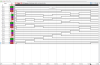
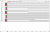
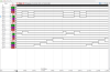
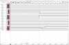
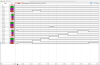
The TMS0974 alternates
in this condition between two completely different Display Scanning Cycles,
resulting in a Flash-Frequency of about 4 Hz:
| • Display on - 16 normal
cycles O7 → O0 (around 75 ms) • Display off - 2 slow-motion cycles in different order (around 175 ms): |
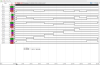
 Scanning: Display and keyboard scanning is performed in
O7 → O0 direction at a rate of about
220 Hz with the O0 State stretched slightly:
Scanning: Display and keyboard scanning is performed in
O7 → O0 direction at a rate of about
220 Hz with the O0 State stretched slightly:
|
• Instruction Cycle Time
(ICT) = 6 Clocks = 0.02 ms @ CK=300 kHz • Active Digit Time O6 → O1 = 189 ICT = 3.78 ms • Active Digit Time O0 = 34 ICT = 0.68 ms • Display Cycle Time = 308 ICT = 4.46 ms |
![]() Device-under-Test:
Device-under-Test:
| • Package Markings Top:
TMS0975NL, ZA0356, AP 7636 • Package Markings Bottom: ⚫DP0975A, SINGAPORE • Donor Product: Little Professor, September 1976 |
Keyboard: The Little Professor makes use of a keyboard with snap-action dome switches arranged in an 4*4 matrix with with the rows connected to the scanning O1-O4 Segment Outputs (Display Scan) and the columns connected to the K1-K8 Inputs (Keyboard Scan) of the TMS0975NL single-chip calculator circuit. While the Little Professor uses the keyboard of the TI-1200 with a 5x4 matrix with the top row masked by the face plate, is the four-position [Level] sliding switch connected to the corresponding O5 Segment Output.
Keyboard Matrix of the Little Professor:
| K1 | K2 | K4 | K8 | |
| O7 (Seg. DP) | ||||
| O6 (Seg. G) | ||||
| O5 (Seg. F) | [L1] | [L2] | [L3] | [L4] |
| O4 (Seg. E) | 7 | 8 | 9 | ÷ |
| O3 (Seg. D) | 4 | 5 | 6 | × |
| O2 (Seg. C) | 1 | 2 | 3 | − |
| O1 (Seg. B) | SET | 0 | GO | + |
| O0 (Seg. A) |
![]() Display: The
Little Professor makes use of a DIS713 Nine-Digit Seven-Segment LED
Display module directly connected to the
corresponding Digit Output pins R0 to R8 (LSD to MSD) and Segment Output pins O0 to O6
(SA to SG). The DIS713 is a modification of the DIS233G Nine-Digit Calculator
Numeric Seven-Segment LED Display module with the 3rd digit position from the
left replaced with a "Star" to display +, −, ×, and ÷ and the
6th position replaced with just two bars to display =. The Decimal
Point is not used with the DIS713.
Display: The
Little Professor makes use of a DIS713 Nine-Digit Seven-Segment LED
Display module directly connected to the
corresponding Digit Output pins R0 to R8 (LSD to MSD) and Segment Output pins O0 to O6
(SA to SG). The DIS713 is a modification of the DIS233G Nine-Digit Calculator
Numeric Seven-Segment LED Display module with the 3rd digit position from the
left replaced with a "Star" to display +, −, ×, and ÷ and the
6th position replaced with just two bars to display =. The Decimal
Point is not used with the DIS713.
Display Layout:
| Texas Instruments DIS713 |
|
|
The Output Decoder PLA of the TMS0975NL (DIP-28) is programmed for 7-Segment displays with the following Output Assignments:
| TMS0975 Pin | 17 | 16 | 15 | 14 | 13 | 12 | 11 | 10 |
| TMS0975 Port | O0 | O1 | O2 | O3 | O4 | O5 | O6 | O7 |
| Segment | A | B | C | D | E | F | G |
| The Segment drivers A-G are connected to the Seven Segment display in the pictured way. | 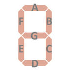   |
Display Fonts:
| Type | Calculator | Number Fonts (R8,R7,R5,R4,R2,R1,R0) |
Operands (R6) |
Equal Sign (R3) |
Wrong Answer |
Game Score |
Idle (R2) |
Memory Indicator |
| TMS0975NL | Little Professor | FLASHING | n.a. |
Looking closer into the Display Fonts used with the Little Professor, you'll notice a total of 18 different patterns (10 Numbers, 4 Operands, Equal Sign, E for Error, Segment G for Idle, and Blank) - beyond the capabilities of the PLA used for the Output Decoder of the TMS0970 and supporting only 16 different inputs.
We looked into the differences between the possible PLA implementation and its visual representation on the Little Professor LED display with a Digilent Digital Discovery Logic Analyzer connected to a TMS0975NL AP operated in the DCM-50A Platform while playing in parallel with an actual Little Professor educational toy.
 After
the tenth math problem the score is "Flashing" on the LED display of the
Little Professor.
The TMS0975NL AP pauses between the Display Scanning Cycles with
a blanked display having only Segment B enabled,
resulting in a Flash-Frequency of about 2.5 Hz at a CK Frequency of 150 kHz:
After
the tenth math problem the score is "Flashing" on the LED display of the
Little Professor.
The TMS0975NL AP pauses between the Display Scanning Cycles with
a blanked display having only Segment B enabled,
resulting in a Flash-Frequency of about 2.5 Hz at a CK Frequency of 150 kHz:
| • Display on - 16 fast
cycles O6 → O0 (around 200 ms) • Display off - Pausing with O0 enabled (around 220 ms) |
 Entering a wrong answer results in the "EEE" message on the Little Professor LED display. The
TMS0975NL AP is actually outputting the Segment Pattern for "EEE" while the
later TMS0975NL GCS is outputting the number 666 but
doesn't scan Segment C resulting in the "EEE" displayed.
Entering a wrong answer results in the "EEE" message on the Little Professor LED display. The
TMS0975NL AP is actually outputting the Segment Pattern for "EEE" while the
later TMS0975NL GCS is outputting the number 666 but
doesn't scan Segment C resulting in the "EEE" displayed.
 During the transition from displaying the math problem and entering a wrong
answer, the Little Professor pauses for a short time and keep the pace of its
Display Scanning Cycle while the later TMS0975NL GCS switches into a much
faster Display Scanning Cycle.
During the transition from displaying the math problem and entering a wrong
answer, the Little Professor pauses for a short time and keep the pace of its
Display Scanning Cycle while the later TMS0975NL GCS switches into a much
faster Display Scanning Cycle.
 In
the moment the pressed key is detected, the Display Scanning Cycle stops
immediately and "freezes" the last active Segment Scanning line to debug the
key. Example shows pressing [8] which is connected between O4 Segment E Output
and K2 Input (KP on DCM-50A Platform).
In
the moment the pressed key is detected, the Display Scanning Cycle stops
immediately and "freezes" the last active Segment Scanning line to debug the
key. Example shows pressing [8] which is connected between O4 Segment E Output
and K2 Input (KP on DCM-50A Platform).
 To save battery power while not in use, the Little Professor changes after a certain time
into an Idle-Mode displaying just a "-" in Digit Position R2. With R2 used
for Numbers, the "-" correspondents to only Segment G activated and the Digilent
Digital Discovery demonstrates this behavior. As of today we can't explain this
discrepancy with the suspected PLA implementation of the TMS0975NL AP.
To save battery power while not in use, the Little Professor changes after a certain time
into an Idle-Mode displaying just a "-" in Digit Position R2. With R2 used
for Numbers, the "-" correspondents to only Segment G activated and the Digilent
Digital Discovery demonstrates this behavior. As of today we can't explain this
discrepancy with the suspected PLA implementation of the TMS0975NL AP.
 Scanning: Display and keyboard scanning is performed in
O6 → O0 direction at a rate of about
80 Hz with one Blank State after O0. The following timing was measured while displaying
" 3+ 4=":
Scanning: Display and keyboard scanning is performed in
O6 → O0 direction at a rate of about
80 Hz with one Blank State after O0. The following timing was measured while displaying
" 3+ 4=":
|
• Instruction Cycle Time
(ICT) = 6 Clocks = 0.04 ms @ CK=150 kHz • Active Digit Time O6 to O0 = 271 ICT = 10.84 ms • Blank State O0 → O6 = 39 ICT = 1.56 ms • Display Cycle Time = 310 ICT = 12.40 ms |
![]() Device-under-Test:
Device-under-Test:
| • Package Markings Top:
TMS0975NL, ZA0356, BP 7640 • Package Markings Bottom: ⚫DP0975B, SINGAPORE • Donor Product: Little Professor, December 1976 |
Keyboard: The Little Professor makes use of a keyboard with snap-action dome switches arranged in an 4*4 matrix with with the rows connected to the scanning O1-O4 Segment Outputs (Display Scan) and the columns connected to the K1-K8 Inputs (Keyboard Scan) of the TMS0975NL single-chip calculator circuit. While the Little Professor uses the keyboard of the TI-1200 with a 5x4 matrix with the top row masked by the face plate, is the four-position [Level] sliding switch connected to the corresponding O5 Segment Output.
Keyboard Matrix of the Little Professor:
| K1 | K2 | K4 | K8 | |
| O7 (Seg. DP) | ||||
| O6 (Seg. G) | ||||
| O5 (Seg. F) | [L1] | [L2] | [L3] | [L4] |
| O4 (Seg. E) | 7 | 8 | 9 | ÷ |
| O3 (Seg. D) | 4 | 5 | 6 | × |
| O2 (Seg. C) | 1 | 2 | 3 | − |
| O1 (Seg. B) | SET | 0 | GO | + |
| O0 (Seg. A) |
![]() Display: The
Little Professor makes use of a DIS713 Nine-Digit Seven-Segment LED
Display module directly connected to the
corresponding Digit Output pins R0 to R8 (LSD to MSD) and Segment Output pins O0 to O6
(SA to SG). The DIS713 is a modification of the DIS233G Nine-Digit Calculator
Numeric Seven-Segment LED Display module with the 3rd digit position from the
left replaced with a "Star" to display +, −, ×, and ÷ and the
6th position replaced with just two bars to display =. The Decimal
Point is not used with the DIS713.
Display: The
Little Professor makes use of a DIS713 Nine-Digit Seven-Segment LED
Display module directly connected to the
corresponding Digit Output pins R0 to R8 (LSD to MSD) and Segment Output pins O0 to O6
(SA to SG). The DIS713 is a modification of the DIS233G Nine-Digit Calculator
Numeric Seven-Segment LED Display module with the 3rd digit position from the
left replaced with a "Star" to display +, −, ×, and ÷ and the
6th position replaced with just two bars to display =. The Decimal
Point is not used with the DIS713.
Display Layout:
| Texas Instruments DIS713 |
|
|
The Output Decoder PLA of the TMS0975NL (DIP-28) is programmed for 7-Segment displays with the following Output Assignments:
| TMS0975 Pin | 17 | 16 | 15 | 14 | 13 | 12 | 11 | 10 |
| TMS0975 Port | O0 | O1 | O2 | O3 | O4 | O5 | O6 | O7 |
| Segment | A | B | C | D | E | F | G |
| The Segment drivers A-G are connected to the Seven Segment display in the pictured way. | |
Display Fonts:
| Type | Calculator | Number Fonts (R8,R7,R5,R4,R2,R1,R0) |
Operands (R6) |
Equal Sign (R3) |
Wrong Answer |
Game Score |
Idle (R2) |
Memory Indicator |
| TMS0975NL | Little Professor | FLASHING | n.a. |
Looking closer into the Display Fonts used with the Little Professor, you'll notice a total of 18 different patterns (10 Numbers, 4 Operands, Equal Sign, E for Error, Segment G for Idle, and Blank) - beyond the capabilities of the PLA used for the Output Decoder of the TMS0970 and supporting only 16 different inputs.
We looked into the differences between the possible PLA implementation and its visual representation on the Little Professor LED display with a Digilent Digital Discovery Logic Analyzer connected to a TMS0975NL BP operated in the DCM-50A Platform while playing in parallel with an actual Little Professor educational toy.
 After
the tenth math problem the score is "Flashing" on the LED display of the
Little Professor.
The TMS0975NL BP pauses between the Display Scanning Cycles with
a blanked display having only Segment B enabled,
resulting in a Flash-Frequency of about 1.25 Hz at a CK Frequency of 150 kHz:
After
the tenth math problem the score is "Flashing" on the LED display of the
Little Professor.
The TMS0975NL BP pauses between the Display Scanning Cycles with
a blanked display having only Segment B enabled,
resulting in a Flash-Frequency of about 1.25 Hz at a CK Frequency of 150 kHz:
| • Display on - 64 fast
cycles O6 → O0 (around 530 ms) • Display off - Pausing with O0 enabled (around 270 ms) |
 Entering
a wrong answer results in the "EEE" message on the Little Professor LED display.
The TMS0975NL BP is like the later TMS0975NL GCS actually outputting the Segment
Pattern for the number 666 but doesn't scan Segment C resulting in the "EEE"
displayed. We observed with the TMS0975NL BP and GCS the following Display
Scanning Sequence: SG on, SF on, SE on, SD on, SC skipped for a dummy SA off, SB
off, and SA on forming the numbers 6.
Entering
a wrong answer results in the "EEE" message on the Little Professor LED display.
The TMS0975NL BP is like the later TMS0975NL GCS actually outputting the Segment
Pattern for the number 666 but doesn't scan Segment C resulting in the "EEE"
displayed. We observed with the TMS0975NL BP and GCS the following Display
Scanning Sequence: SG on, SF on, SE on, SD on, SC skipped for a dummy SA off, SB
off, and SA on forming the numbers 6.
 During the transition from displaying the math problem and entering a wrong
answer, the Little Professor pauses for a short time and switches into a much
faster
Display Scanning Cycle while the earlier TMS0975NL AP keep the pace of its Display Scanning Cycle.
During the transition from displaying the math problem and entering a wrong
answer, the Little Professor pauses for a short time and switches into a much
faster
Display Scanning Cycle while the earlier TMS0975NL AP keep the pace of its Display Scanning Cycle.
 In
the moment the pressed key is detected, the Display Scanning Cycle stops
immediately and "freezes" the last active Segment Scanning line to debug the
key. Example shows pressing [8] which is connected between O4 Segment E Output
and K2 Input (KP on DCM-50A Platform).
In
the moment the pressed key is detected, the Display Scanning Cycle stops
immediately and "freezes" the last active Segment Scanning line to debug the
key. Example shows pressing [8] which is connected between O4 Segment E Output
and K2 Input (KP on DCM-50A Platform).
 To
save battery power while not in use, the Little Professor changes after a
certain time into an Idle-Mode displaying just a "-" in Digit Position R2. With R2 used
for Numbers, the "-" correspondents to only Segment G activated and the Digilent
Digital Discovery demonstrates this behavior. As of today we can't explain this
discrepancy with the suspected PLA implementation of the TMS0975NL BP.
To
save battery power while not in use, the Little Professor changes after a
certain time into an Idle-Mode displaying just a "-" in Digit Position R2. With R2 used
for Numbers, the "-" correspondents to only Segment G activated and the Digilent
Digital Discovery demonstrates this behavior. As of today we can't explain this
discrepancy with the suspected PLA implementation of the TMS0975NL BP.
 Scanning: Display and keyboard scanning is performed in
O6 → O0 direction at a rate of about
60 Hz with one Blank State after O0 and slightly different timing for the individual OX States depending on
the content of the display. The following timing was measured while displaying
" 1+ 4=":
Scanning: Display and keyboard scanning is performed in
O6 → O0 direction at a rate of about
60 Hz with one Blank State after O0 and slightly different timing for the individual OX States depending on
the content of the display. The following timing was measured while displaying
" 1+ 4=":
|
• Instruction Cycle Time (ICT) = 6 Clocks = 0.04 ms @ CK=150 kHz • Active Digit Time O6 = 59 ICT = 2.36 ms • Active Digit Time O5 = 46 ICT = 1.84 ms • Active Digit Time O4 = 62 ICT = 2.48 ms • Active Digit Time O3 = 56 ICT = 2.24 ms • Active Digit Time O2 = 62 ICT = 2.48 ms • Active Digit Time O1 = 65 ICT = 2.60 ms • Active Digit Time O0 = 28 ICT = 1.12 ms • Blank State O0 → O6 = 43 ICT = 1.72 ms • Display Cycle Time = 421 ICT = 16.84 ms |
 Device-under-Test:
| • Package Markings Top:
TMS0975NL, ZA0356, CSP 7814 • Package Markings Bottom: ⚫GP0975CS, SINGAPORE • Donor Product: Little Professor, May 1978 |
Keyboard: The Little Professor makes use of a keyboard with snap-action dome switches arranged in an 4*4 matrix with with the rows connected to the scanning O1-O4 Segment Outputs (Display Scan) and the columns connected to the K1-K8 Inputs (Keyboard Scan) of the TMS0975NL single-chip calculator circuit. The Little Professor uses the keyboard of the TI-1200 with a 5x4 matrix but the top row is masked by the face plate. The four-position [Level] sliding switch connected to the O7 Segment Output.
Keyboard Matrix of the Little Professor:
| K1 | K2 | K4 | K8 | |
| O7 (Seg. DP) | [L1] | [L2] | [L3] | [L4] |
| O6 (Seg. G) | ||||
| O5 (Seg. F) | ||||
| O4 (Seg. E) | 7 | 8 | 9 | ÷ |
| O3 (Seg. D) | 4 | 5 | 6 | × |
| O2 (Seg. C) | 1 | 2 | 3 | − |
| O1 (Seg. B) | SET | 0 | GO | + |
| O0 (Seg. A) |
![]() Display: The
Little Professor makes use of a DIS713 Nine-Digit Seven-Segment LED
Display module directly connected to the
corresponding Digit Output pins R0 to R8 (LSD to MSD) and Segment Output pins O0 to O6
(SA to SG). The DIS713 is a modification of the DIS233G Nine-Digit Calculator
Numeric Seven-Segment LED Display module with the 3rd digit position from the
left replaced with a "Star" to display +, −, ×, and ÷ and the
6th position replaced with just two bars to display =. The Decimal
Point is not used with the DIS713.
Display: The
Little Professor makes use of a DIS713 Nine-Digit Seven-Segment LED
Display module directly connected to the
corresponding Digit Output pins R0 to R8 (LSD to MSD) and Segment Output pins O0 to O6
(SA to SG). The DIS713 is a modification of the DIS233G Nine-Digit Calculator
Numeric Seven-Segment LED Display module with the 3rd digit position from the
left replaced with a "Star" to display +, −, ×, and ÷ and the
6th position replaced with just two bars to display =. The Decimal
Point is not used with the DIS713.
Display Layout:
| Texas Instruments DIS713 |
|
|
The Output Decoder PLA of the TMS0975NL (SPDIP-28) is programmed for 7-Segment displays with the following Output Assignments:
| TMS0975 Pin | 18 | 17 | 16 | 15 | 13 | 12 | 11 | 10 |
| TMS0975 Port | O0 | O1 | O2 | O3 | O4 | O5 | O6 | O7 |
| Segment | A | B | C | D | E | F | G | DP |
| The Segment drivers A-G are connected to the Seven Segment display in the pictured way. The Decimal Point is not used. | |
Display Fonts:
| Type | Calculator | Number Fonts (R8,R7,R5,R4,R2,R1,R0) |
Operands (R6) |
Equal Sign (R3) |
Wrong Answer |
Game Score |
Idle (R2) |
Memory Indicator |
| TMS0975NL | Little Professor | FLASHING | n.a. |
Looking closer into the Display Fonts used with the Little Professor, you'll notice a total of 18 different patterns (10 Numbers, 4 Operands, Equal Sign, E for Error, Segment G for Idle, and Blank) - beyond the capabilities of the PLA used for the Output Decoder of the TMS0970 and supporting only 16 different inputs. Sean Riddle analyzed the physical implementation of the TMS0975NL CSP PLA and it uses indeed only 16 different patterns:
| PLA Term# |
Output DP A B C D E F G |
Segment Pattern |
Comments |
| 0 | 1 1 1 1 1 1 1 0 | Number Font 0 | |
| 1 | 1 0 1 1 0 0 0 0 | Number Font 1 | |
| 2 | 1 1 1 0 1 1 0 1 | Number Font 2 | |
| 3 | 1 1 1 1 1 0 0 1 | Number Font 3 | |
| 4 | 1 0 1 1 0 0 1 1 | Number Font 4 | |
| 5 | 1 1 0 1 1 0 1 1 | Number Font 5 | |
| 6 | 1 1 0 1 1 1 1 1 | Number Font 6 | |
| 7 | 1 1 1 1 0 0 0 0 | Number Font 7 | |
| 8 | 1 1 1 1 1 1 1 1 | Number Font 8 | |
| 9 | 1 1 1 1 1 0 1 1 | Number Font 9 | |
| 10 | 0 0 1 0 0 1 1 0 | Operand Font + | |
| 11 | 0 0 0 0 0 0 1 0 | Operand Font − | |
| 12 | 0 0 1 1 0 1 0 1 | Operand Font × | |
| 13 | 0 1 0 0 1 0 1 0 | Operand Font ÷ | |
| 14 | 0 1 0 0 0 0 0 1 |
|
Equal Sign Font = |
| 15 | 0 0 0 0 0 0 0 0 | Blank Pattern |
We analyzed the differences between the actual PLA implementation and its visual representation on the Little Professor LED display with a Digilent Digital Discovery Logic Analyzer connected to a TMS0975NL CSP operated in the DCM-50A Platform while playing in parallel with an actual Little Professor educational toy.
 After
the tenth math problem the score is "Flashing" on the LED display of the
Little Professor.
The TMS0975NL CSP pauses between the Display Scanning Cycles with
a blanked display having only Segment B enabled,
resulting in a Flash-Frequency of about 1 Hz at a CK Frequency of 150 kHz:
After
the tenth math problem the score is "Flashing" on the LED display of the
Little Professor.
The TMS0975NL CSP pauses between the Display Scanning Cycles with
a blanked display having only Segment B enabled,
resulting in a Flash-Frequency of about 1 Hz at a CK Frequency of 150 kHz:
| • Display on - 64 fast
cycles O7 → O0 (around 530 ms) • Display off - Pausing with O1 enabled (around 375 ms) |
 Entering a wrong answer results in the "EEE" message on the Little Professor LED display. The
TMS0975NL CSP is actually outputting the Segment Pattern for the number 666 but
doesn't scan Segment C resulting in the "EEE" displayed.
Entering a wrong answer results in the "EEE" message on the Little Professor LED display. The
TMS0975NL CSP is actually outputting the Segment Pattern for the number 666 but
doesn't scan Segment C resulting in the "EEE" displayed.
 During the transition from displaying the math problem and entering a wrong
answer, the Little Professor pauses for a short time and switches into a much
faster Display Scanning Cycle.
During the transition from displaying the math problem and entering a wrong
answer, the Little Professor pauses for a short time and switches into a much
faster Display Scanning Cycle.
 In
the moment the pressed key is detected, the Display Scanning Cycle stops
immediately and "freezes" the last active Segment Scanning line to debug the
key. Example shows pressing [8] which is connected between O4 Segment E Output
and K2 Input (KP on DCM-50A Platform).
In
the moment the pressed key is detected, the Display Scanning Cycle stops
immediately and "freezes" the last active Segment Scanning line to debug the
key. Example shows pressing [8] which is connected between O4 Segment E Output
and K2 Input (KP on DCM-50A Platform).
 To save battery power while not in use, the Little Professor changes after a certain time
into an Idle-Mode displaying just a "-" in Digit Position R2. With R2 used
for Numbers, the "-" correspondents to only Segment G activated and the Digilent
Digital Discovery demonstrates this behavior. As of today we can't explain this
discrepancy with the actual PLA implementation of the TMS0975NL CSP.
To save battery power while not in use, the Little Professor changes after a certain time
into an Idle-Mode displaying just a "-" in Digit Position R2. With R2 used
for Numbers, the "-" correspondents to only Segment G activated and the Digilent
Digital Discovery demonstrates this behavior. As of today we can't explain this
discrepancy with the actual PLA implementation of the TMS0975NL CSP.
 Scanning: Display and keyboard scanning is performed in
O7 → O0 direction at a rate of about
60 Hz with slightly different timing for the individual OX States depending on
the content of the display. The following timing was measured while displaying
" 5+ 4=":
Scanning: Display and keyboard scanning is performed in
O7 → O0 direction at a rate of about
60 Hz with slightly different timing for the individual OX States depending on
the content of the display. The following timing was measured while displaying
" 5+ 4=":
|
• Instruction Cycle Time
(ICT) = 6 Clocks = 0.04 ms @ CK=150 kHz • Active Digit Time O7 = 46 ICT = 1.84 ms • Active Digit Time O6 = 56 ICT = 2.24 ms • Active Digit Time O5 = 46 ICT = 1.84 ms • Active Digit Time O4 = 62 ICT = 2.48 ms • Active Digit Time O3 = 59 ICT = 2.36 ms • Active Digit Time O2 = 62 ICT = 2.48 ms • Active Digit Time O1 = 68 ICT = 2.72 ms • Active Digit Time O0 = 28 ICT = 1.12 ms • Display Cycle Time = 427 ICT = 17.08 ms |
 Device-under-Test:
| • Package Markings Top:
TMS0975NL, ZA0356, GCS 7827, SINGAPORE • Package Markings Bottom: • Donor Product: Little Professor, September 1978 |
Keyboard: The Little Professor makes use of a keyboard with snap-action dome switches arranged in an 4*4 matrix with with the rows connected to the scanning O1-O4 Segment Outputs (Display Scan) and the columns connected to the K1-K8 Inputs (Keyboard Scan) of the TMS0975NL single-chip calculator circuit. The Little Professor uses the keyboard of the TI-1200 with a 5x4 matrix but the top row is masked by the face plate. The four-position [Level] sliding switch connected to the O7 Segment Output.
Keyboard Matrix of the Little Professor:
| K1 | K2 | K4 | K8 | |
| O7 (Seg. DP) | [L1] | [L2] | [L3] | [L4] |
| O6 (Seg. G) | ||||
| O5 (Seg. F) | ||||
| O4 (Seg. E) | 7 | 8 | 9 | ÷ |
| O3 (Seg. D) | 4 | 5 | 6 | × |
| O2 (Seg. C) | 1 | 2 | 3 | − |
| O1 (Seg. B) | SET | 0 | GO | + |
| O0 (Seg. A) |
![]() Display: The
Little Professor makes use of a DIS713 Nine-Digit Seven-Segment LED
Display module directly connected to the
corresponding Digit Output pins R0 to R8 (LSD to MSD) and Segment Output pins O0 to O6
(SA to SG). The DIS713 is a modification of the DIS233G Nine-Digit Calculator
Numeric Seven-Segment LED Display module with the 3rd digit position from the
left replaced with a "Star" to display +, −, ×, and ÷ and the
6th position replaced with just two bars to display =. The Decimal
Point is not used with the DIS713.
Display: The
Little Professor makes use of a DIS713 Nine-Digit Seven-Segment LED
Display module directly connected to the
corresponding Digit Output pins R0 to R8 (LSD to MSD) and Segment Output pins O0 to O6
(SA to SG). The DIS713 is a modification of the DIS233G Nine-Digit Calculator
Numeric Seven-Segment LED Display module with the 3rd digit position from the
left replaced with a "Star" to display +, −, ×, and ÷ and the
6th position replaced with just two bars to display =. The Decimal
Point is not used with the DIS713.
Display Layout:
| Texas Instruments DIS713 |
|
|
The Output Decoder PLA of the TMS0975NL (SPDIP-28) is programmed for 7-Segment displays with the following Output Assignments:
| TMS0975 Pin | 18 | 17 | 16 | 15 | 13 | 12 | 11 | 10 |
| TMS0975 Port | O0 | O1 | O2 | O3 | O4 | O5 | O6 | O7 |
| Segment | A | B | C | D | E | F | G | DP |
| The Segment drivers A-G are connected to the Seven Segment display in the pictured way. The Decimal Point is not used. | |
Display Fonts:
| Type | Calculator | Number Fonts (R8,R7,R5,R4,R2,R1,R0) |
Operands (R6) |
Equal Sign (R3) |
Wrong Answer |
Game Score |
Idle (R2) |
Memory Indicator |
| TMS0975NL | Little Professor | FLASHING | n.a. |
Looking closer into the Display Fonts used with the Little Professor, you'll notice a total of 18 different patterns (10 Numbers, 4 Operands, Equal Sign, E for Error, Segment G for Idle, and Blank) - beyond the capabilities of the PLA used for the Output Decoder of the TMS0970 and supporting only 16 different inputs. Sean Riddle analyzed the physical implementation of the TMS0975NL GCS PLA and it uses indeed only 16 different patterns:
| PLA Term# |
Output DP A B C D E F G |
Segment Pattern |
Comments |
| 0 | 1 1 1 1 1 1 1 0 | Number Font 0 | |
| 1 | 1 0 1 1 0 0 0 0 | Number Font 1 | |
| 2 | 1 1 1 0 1 1 0 1 | Number Font 2 | |
| 3 | 1 1 1 1 1 0 0 1 | Number Font 3 | |
| 4 | 1 0 1 1 0 0 1 1 | Number Font 4 | |
| 5 | 1 1 0 1 1 0 1 1 | Number Font 5 | |
| 6 | 1 1 0 1 1 1 1 1 | Number Font 6 | |
| 7 | 1 1 1 1 0 0 0 0 | Number Font 7 | |
| 8 | 1 1 1 1 1 1 1 1 | Number Font 8 | |
| 9 | 1 1 1 1 1 0 1 1 | Number Font 9 | |
| 10 | 0 0 1 0 0 1 1 0 | Operand Font + | |
| 11 | 0 0 0 0 0 0 1 0 | Operand Font − | |
| 12 | 0 0 1 1 0 1 0 1 | Operand Font × | |
| 13 | 0 1 0 0 1 0 1 0 | Operand Font ÷ | |
| 14 | 0 1 0 0 0 0 0 1 |
|
Equal Sign Font = |
| 15 | 0 0 0 0 0 0 0 0 | Blank Pattern |
We analyzed the differences between the actual PLA implementation and its visual representation on the Little Professor LED display with a Digilent Digital Discovery Logic Analyzer connected to a TMS0975NL GCS operated in the DCM-50A Platform while playing in parallel with an actual Little Professor educational toy.
After
the tenth math problem the score is "Flashing" on the LED display of the
Little Professor.
The TMS0975NL GCS pauses between the Display Scanning Cycles with
a blanked display having only Segment B enabled,
resulting in a Flash-Frequency of about 1 Hz at a CK Frequency of 150 kHz:
| • Display on - 64 fast
cycles O7 → O0 (around 530 ms) • Display off - Pausing with O1 enabled (around 375 ms) |
Entering a wrong answer results in the "EEE" message on the Little Professor LED display. The
TMS0975NL GCS is actually outputting the Segment Pattern for the number 666 but
doesn't scan Segment C resulting in the "EEE" displayed.
During the transition from displaying the math problem and entering a wrong
answer, the Little Professor pauses for a short time and switches into a much
faster Display Scanning Cycle.
In
the moment the pressed key is detected, the Display Scanning Cycle stops
immediately and "freezes" the last active Segment Scanning line to debug the
key. Example shows pressing [8] which is connected between O4 Segment E Output
and K2 Input (KP on DCM-50A Platform).
To save battery power while not in use, the Little Professor changes after a certain time
into an Idle-Mode displaying just a "-" in Digit Position R2. With R2 used
for Numbers, the "-" correspondents to only Segment G activated and the Digilent
Digital Discovery demonstrates this behavior. As of today we can't explain this
discrepancy with the actual PLA implementation of the TMS0975NL GCS.
Scanning: Display and keyboard scanning is performed in
O7 → O0 direction at a rate of about
60 Hz with slightly different timing for the individual OX States depending on
the content of the display. The following timing was measured while displaying
" 0+ 3=":
|
• Instruction Cycle Time
(ICT) = 6 Clocks = 0.04 ms @ CK=150 kHz • Active Digit Time O7 = 46 ICT = 1.84 ms • Active Digit Time O6 = 56 ICT = 2.24 ms • Active Digit Time O5 = 46 ICT = 1.84 ms • Active Digit Time O4 = 62 ICT = 2.48 ms • Active Digit Time O3 = 59 ICT = 2.36 ms • Active Digit Time O2 = 62 ICT = 2.48 ms • Active Digit Time O1 = 68 ICT = 2.72 ms • Active Digit Time O0 = 28 ICT = 1.12 ms • Display Cycle Time = 427 ICT = 17.08 ms |
 Device-under-Test:
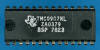
| • Package Markings Top:
TMC0907NL, ZA0379, BSP 7823 • Package Markings Bottom: ⚫DP0907BS, SINGAPORE • Donor Product: WIZ-A-TRON, June 1978 |
Keyboard: The WIZ-A-TRON makes use of a keyboard with snap-action dome switches arranged in an 4*4 matrix with with the rows connected to the scanning O1-O4 Segment Outputs (Display Scan) and the columns connected to the K1-K8 Inputs (Keyboard Scan) of the TMC0907NL single-chip calculator circuit.
Keyboard Matrix of the WIZ-A-TRON:
| K1 | K2 | K4 | K8 | |
| O7 (Seg. DP) | ||||
| O6 (Seg. G) | ||||
| O5 (Seg. F) | ||||
| O4 (Seg. E) | 7 | 8 | 9 | ÷ |
| O3 (Seg. D) | 4 | 5 | 6 | × |
| O2 (Seg. C) | 1 | 2 | 3 | − |
| O1 (Seg. B) | CLEAR | 0 | = | + |
| O0 (Seg. A) |
![]() Display: The
WIZ-A-TRON makes use of a DIS713 Nine-Digit Seven-Segment LED
Display module directly connected to the
corresponding Digit Output pins R0 to R8 (LSD to MSD) and Segment Output pins O0 to O6
(SA to SG). The DIS713 is a modification of the DIS233G Nine-Digit Calculator
Numeric Seven-Segment LED Display module with the 3rd digit position from the
left replaced with a "Star" to display +, −, ×, and ÷ and the
6th position replaced with just two bars to display =. The Decimal
Point is not used with the DIS713.
Display: The
WIZ-A-TRON makes use of a DIS713 Nine-Digit Seven-Segment LED
Display module directly connected to the
corresponding Digit Output pins R0 to R8 (LSD to MSD) and Segment Output pins O0 to O6
(SA to SG). The DIS713 is a modification of the DIS233G Nine-Digit Calculator
Numeric Seven-Segment LED Display module with the 3rd digit position from the
left replaced with a "Star" to display +, −, ×, and ÷ and the
6th position replaced with just two bars to display =. The Decimal
Point is not used with the DIS713.
Display Layout:
| Texas Instruments DIS713 |
|
|
The Output Decoder PLA of the TMC0907NL is programmed for 7-Segment displays with the following Output Assignments:
| TMC0907 Pin | 18 | 17 | 16 | 15 | 13 | 12 | 11 | 10 |
| TMC0907 Port | O0 | O1 | O2 | O3 | O4 | O5 | O6 | O7 |
| Segment | A | B | C | D | E | F | G |
| The Segment drivers A-G are connected to the Seven Segment display in the pictured way. | |
Display Fonts:
| Type | Calculator | Number Fonts (R8,R7,R5,R4,R2,R1,R0) |
Operands (R6) |
Equal Sign (R3) |
Wrong Answer |
Correct Answer |
Idle (R2) |
Memory Indicator |
| TMC0907NL | WIZ-A-TRON | FLASHING | n.a. |
Looking closer into the Display Fonts used with the WIZ-A-TRON, you'll notice a total of 18 different patterns (10 Numbers, 4 Operands, Equal Sign, E for Error, Segment G for Idle, and Blank) - beyond the capabilities of the PLA used for the Output Decoder of the TMS0970 and supporting only 16 different inputs. Sean Riddle analyzed the physical implementation of the TMC0907NL PLA and it uses indeed only 16 different patterns:
| PLA Term# |
Output DP A B C D E F G |
Segment Pattern |
Comments |
| 0 | 0 1 1 1 1 1 1 0 | Number Font 0 | |
| 1 | 0 0 1 1 0 0 0 0 | Number Font 1 | |
| 2 | 0 1 1 0 1 1 0 1 | Number Font 2 | |
| 3 | 0 1 1 1 1 0 0 1 | Number Font 3 | |
| 4 | 0 0 1 1 0 0 1 1 | Number Font 4 | |
| 5 | 0 1 0 1 1 0 1 1 | Number Font 5 | |
| 6 | 0 1 0 1 1 1 1 1 | Number Font 6 | |
| 7 | 0 1 1 1 0 0 0 0 | Number Font 7 | |
| 8 | 0 1 1 1 1 1 1 1 | Number Font 8 | |
| 9 | 0 1 1 1 1 0 1 1 | Number Font 9 | |
| 10 | 0 0 1 0 0 1 1 0 | Operand Font + | |
| 11 | 0 0 0 0 0 0 1 0 | Operand Font − | |
| 12 | 0 0 1 1 0 1 0 1 | Operand Font × | |
| 13 | 0 1 0 0 1 0 1 0 | Operand Font ÷ | |
| 14 | 0 0 0 0 0 1 0 1 | Unused r (Error?) | |
| 15 | 0 0 0 0 0 0 0 0 | Blank Pattern |
We analyzed the differences between the actual PLA implementation and its visual representation on the WIZ-A-TRON LED display with a Digilent Digital Discovery Logic Analyzer connected to a TMC0907NL operated in the DCM-50A Platform while playing in parallel with an actual WIZ-A-TRON educational toy.
 After
Power-up the WIZ-A-TRON is greeting the user with an Equal Sign in Digit
Position R3. The TMC0907 is actually outputting the Segment Pattern for the
number 8 but the DIS713 LED display is populated for this Digit Position with
only the two bars forming the Equal Sign.
After
Power-up the WIZ-A-TRON is greeting the user with an Equal Sign in Digit
Position R3. The TMC0907 is actually outputting the Segment Pattern for the
number 8 but the DIS713 LED display is populated for this Digit Position with
only the two bars forming the Equal Sign.
 Entering
a wrong answer results in the "EEE" message on the WIZ-A-TRON LED display. The
TMC0907 is actually outputting the Segment Pattern for the number 666 but
doesn't scan Segment C resulting in the "EEE" displayed.
Entering
a wrong answer results in the "EEE" message on the WIZ-A-TRON LED display. The
TMC0907 is actually outputting the Segment Pattern for the number 666 but
doesn't scan Segment C resulting in the "EEE" displayed.
 Entering
a correct answer results in a "Flashing" display on the WIZ-A-TRON.
The TMC0907 alternates between two completely different Display Scanning Cycles,
a blanked display uses only Segments B, C, D, and E scanning is preformed at a very low
frequency.
Entering
a correct answer results in a "Flashing" display on the WIZ-A-TRON.
The TMC0907 alternates between two completely different Display Scanning Cycles,
a blanked display uses only Segments B, C, D, and E scanning is preformed at a very low
frequency.
 To
save battery power while not in use, the WIZ-A-TRON changes after a certain time
into an Idle-Mode displaying just a "-" in Digit Position R2. With R2 used
for Numbers, the "-" correspondents to only Segment G activated and the Digilent
Digital Discovery demonstrates this behavior. As of today we can't explain this
discrepancy with the actual PLA implementation of the TMC0907.
To
save battery power while not in use, the WIZ-A-TRON changes after a certain time
into an Idle-Mode displaying just a "-" in Digit Position R2. With R2 used
for Numbers, the "-" correspondents to only Segment G activated and the Digilent
Digital Discovery demonstrates this behavior. As of today we can't explain this
discrepancy with the actual PLA implementation of the TMC0907.
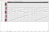
 Scanning: Display and keyboard scanning is performed in
O7 → O0 direction at a rate of about
160 Hz with slightly different timing for the individual OX States depending on
the content of the display. The following timing was measured while displaying
"12+34=":
Scanning: Display and keyboard scanning is performed in
O7 → O0 direction at a rate of about
160 Hz with slightly different timing for the individual OX States depending on
the content of the display. The following timing was measured while displaying
"12+34=":
|
• Instruction Cycle Time
(ICT) = 6 Clocks = 0.02 ms @ CK=300 kHz • Active Digit Time O7 = 34 ICT = 0.68 ms • Active Digit Time O6 = 34 ICT = 0.68 ms • Active Digit Time O5 = 34 ICT = 0.68 ms • Active Digit Time O4 = 40 ICT = 0.80 ms • Active Digit Time O3 = 40 ICT = 0.80 ms • Active Digit Time O2 = 40 ICT = 0.80 ms • Active Digit Time O1 = 56 ICT = 1.12 ms • Active Digit Time O0 = 28 ICT = 0.56 ms • Display Cycle Time = 306 ICT = 6.12 ms |
 Device-under-Test:
| • Package Markings Top:
TMC0907NL, ZA0379, DBS 7845 SINGAPORE • Package Markings Bottom: • Donor Product: WIZ-A-TRON, December 1978 |
Keyboard: The WIZ-A-TRON makes use of a keyboard with snap-action dome switches arranged in an 4*4 matrix with with the rows connected to the scanning O1-O4 Segment Outputs (Display Scan) and the columns connected to the K1-K8 Inputs (Keyboard Scan) of the TMC0907NL single-chip calculator circuit.
Keyboard Matrix of the WIZ-A-TRON:
| K1 | K2 | K4 | K8 | |
| O7 (Seg. DP) | ||||
| O6 (Seg. G) | ||||
| O5 (Seg. F) | ||||
| O4 (Seg. E) | 7 | 8 | 9 | ÷ |
| O3 (Seg. D) | 4 | 5 | 6 | × |
| O2 (Seg. C) | 1 | 2 | 3 | − |
| O1 (Seg. B) | CLEAR | 0 | = | + |
| O0 (Seg. A) |
![]() Display: The
WIZ-A-TRON makes use of a DIS713 Nine-Digit Seven-Segment LED
Display module directly connected to the
corresponding Digit Output pins R0 to R8 (LSD to MSD) and Segment Output pins O0 to O6
(SA to SG). The DIS713 is a modification of the DIS233G Nine-Digit Calculator
Numeric Seven-Segment LED Display module with the 3rd digit position from the
left replaced with a "Star" to display +, −, ×, and ÷ and the
6th position replaced with just two bars to display =. The Decimal
Point is not used with the DIS713.
Display: The
WIZ-A-TRON makes use of a DIS713 Nine-Digit Seven-Segment LED
Display module directly connected to the
corresponding Digit Output pins R0 to R8 (LSD to MSD) and Segment Output pins O0 to O6
(SA to SG). The DIS713 is a modification of the DIS233G Nine-Digit Calculator
Numeric Seven-Segment LED Display module with the 3rd digit position from the
left replaced with a "Star" to display +, −, ×, and ÷ and the
6th position replaced with just two bars to display =. The Decimal
Point is not used with the DIS713.
Display Layout:
| Texas Instruments DIS713 |
|
|
The Output Decoder PLA of the TMC0907NL is programmed for 7-Segment displays with the following Output Assignments:
| TMC0907 Pin | 18 | 17 | 16 | 15 | 13 | 12 | 11 | 10 |
| TMC0907 Port | O0 | O1 | O2 | O3 | O4 | O5 | O6 | O7 |
| Segment | A | B | C | D | E | F | G |
| The Segment drivers A-G are connected to the Seven Segment display in the pictured way. | |
Display Fonts:
| Type | Calculator | Number Fonts (R8,R7,R5,R4,R2,R1,R0) |
Operands (R6) |
Equal Sign (R3) |
Wrong Answer |
Correct Answer |
Idle (R2) |
Memory Indicator |
| TMC0907NL | WIZ-A-TRON | FLASHING | n.a. |
Looking closer into the Display Fonts used with the WIZ-A-TRON, you'll notice a total of 18 different patterns (10 Numbers, 4 Operands, Equal Sign, E for Error, Segment G for Idle, and Blank) - beyond the capabilities of the PLA used for the Output Decoder of the TMS0970 and supporting only 16 different inputs. Sean Riddle analyzed the physical implementation of the TMC0907NL PLA and it uses indeed only 16 different patterns:
| PLA Term# |
Output DP A B C D E F G |
Segment Pattern |
Comments |
| 0 | 0 1 1 1 1 1 1 0 | Number Font 0 | |
| 1 | 0 0 1 1 0 0 0 0 | Number Font 1 | |
| 2 | 0 1 1 0 1 1 0 1 | Number Font 2 | |
| 3 | 0 1 1 1 1 0 0 1 | Number Font 3 | |
| 4 | 0 0 1 1 0 0 1 1 | Number Font 4 | |
| 5 | 0 1 0 1 1 0 1 1 | Number Font 5 | |
| 6 | 0 1 0 1 1 1 1 1 | Number Font 6 | |
| 7 | 0 1 1 1 0 0 0 0 | Number Font 7 | |
| 8 | 0 1 1 1 1 1 1 1 | Number Font 8 | |
| 9 | 0 1 1 1 1 0 1 1 | Number Font 9 | |
| 10 | 0 0 1 0 0 1 1 0 | Operand Font + | |
| 11 | 0 0 0 0 0 0 1 0 | Operand Font − | |
| 12 | 0 0 1 1 0 1 0 1 | Operand Font × | |
| 13 | 0 1 0 0 1 0 1 0 | Operand Font ÷ | |
| 14 | 0 0 0 0 0 1 0 1 | Unused r (Error?) | |
| 15 | 0 0 0 0 0 0 0 0 | Blank Pattern |
We analyzed the differences between the actual PLA implementation and its visual representation on the WIZ-A-TRON LED display with a Digilent Digital Discovery Logic Analyzer connected to a TMC0907NL operated in the DCM-50A Platform while playing in parallel with an actual WIZ-A-TRON educational toy.
After
Power-up the WIZ-A-TRON is greeting the user with an Equal Sign in Digit
Position R3. The TMC0907 is actually outputting the Segment Pattern for the
number 8 but the DIS713 LED display is populated for this Digit Position with
only the two bars forming the Equal Sign.
Entering
a wrong answer results in the "EEE" message on the WIZ-A-TRON LED display. The
TMC0907 is actually outputting the Segment Pattern for the number 666 but
doesn't scan Segment C resulting in the "EEE" displayed.
Entering
a correct answer results in a "Flashing" display on the WIZ-A-TRON.
The TMC0907 alternates between two completely different Display Scanning Cycles,
a blanked display uses only Segments B, C, D, and E scanning is preformed at a very low
frequency.
To
save battery power while not in use, the WIZ-A-TRON changes after a certain time
into an Idle-Mode displaying just a "-" in Digit Position R2. With R2 used
for Numbers, the "-" correspondents to only Segment G activated and the Digilent
Digital Discovery demonstrates this behavior. As of today we can't explain this
discrepancy with the actual PLA implementation of the TMC0907.
 Scanning: Display and keyboard scanning is performed in
O7 → O0 direction at a rate of about
160 Hz with slightly different timing for the individual OX States depending on
the content of the display. The following timing was measured while displaying
"12+34=":
Scanning: Display and keyboard scanning is performed in
O7 → O0 direction at a rate of about
160 Hz with slightly different timing for the individual OX States depending on
the content of the display. The following timing was measured while displaying
"12+34=":
|
• Instruction Cycle Time
(ICT) = 6 Clocks = 0.02 ms @ CK=300 kHz • Active Digit Time O7 = 34 ICT = 0.68 ms • Active Digit Time O6 = 34 ICT = 0.68 ms • Active Digit Time O5 = 34 ICT = 0.68 ms • Active Digit Time O4 = 40 ICT = 0.80 ms • Active Digit Time O3 = 40 ICT = 0.80 ms • Active Digit Time O2 = 40 ICT = 0.80 ms • Active Digit Time O1 = 56 ICT = 1.12 ms • Active Digit Time O0 = 28 ICT = 0.56 ms • Display Cycle Time = 306 ICT = 6.12 ms |
If you have additions to the above article please email: joerg@datamath.org.
© Joerg Woerner, October 8, 2023. No reprints without written permission.