DATAMATH CALCULATOR MUSEUM
|
|
DATAMATH CALCULATOR MUSEUM |
Characterization of Single-chip Calculator Circuits - TMS0100 Product Family
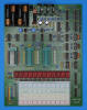
The DCM-50A Platform supports the Characterization of TMS0100 Devices including TMS1802 and TMS1875 in its leftmost TMS0100 Textool Test Socket with the voltages VSS set to 7.2V and VGG set to -7.2V, accordingly.
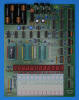
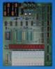
![]() Device-under-Test:
Device-under-Test:
| • Package Markings Top: TMS1875NC,
7227 • Package Markings Bottom: 11983 • Donor Calculator: Heathkit IC-2008, March 1972 |
Keyboard: The Heathkit IC-2008 makes use of a keyboard assembled with individual long-stroke push-button switches arranged in an 11*2 matrix with the rows connected to the D1-D11 Outputs (Display Scan) and the columns connected to the KN (Keyboard Scan Numerical) and KO (Keyboard Scan Operational) Inputs of the TMS1875NC single-chip calculator circuit. The thumb-wheel switch to select the position of the decimal point is connected between the D1-D7 and D10 Output and KP (Keyboard Scan Decimal Point) Input while the latching push-button switch for the Constant Mode is connected between the D10 Output and KQ (Keyboard Scan Constant) Input.
Keyboard Matrix of the Heathkit IC-2008:
TMS1875 |
||||
| KN | KO | KP | KQ | |
| D1 | 1 | + | [F-DP1] | |
| D2 | 2 | × | [F-DP2] | |
| D3 | 3 | ÷ | [F-DP3] | |
| D4 | 4 | − | [F-DP4] | |
| D5 | 5 | [F-DP5] | ||
| D6 | 6 | [F-DP6] | ||
| D7 | 7 | +/− | [F-DP7] | |
| D8 | 8 | = | ||
| D9 | 9 | . | ||
| D10 | 0 | CE | [F-DP0] | [C-K] |
| D11 | C | |||
 Display: The
Heathkit IC-2008 makes use of a 9-digit display assembly with three 3-digit
Sperry SP-753 planar neon gas discharge "Panaplex II" display modules. The nine
discrete high-voltage drivers for the Anodes of the display assembly are
connected to the D1-D8 and D11 Outputs (Display Scan) of the TMS1875NC and the 8
discrete high-voltage drivers for the Cathodes to its SA-SG and SP Outputs
(Segments) with SH not connected. An additional flip-flop with its clock input
connected to the Digit Driver output D11 of the TMS1875NC used for the left-most
digit and its two Q and /Q outputs connected to the eight discrete high-voltage
drivers. This circuitry changes the pre-programmed scanning order of the
TMS1875NC from D11→D10→D9…D1 to D11→D10→D8...D2 / D11→D9→D7…D1 (with D10 and D9
actually not used for the display of an 8-digit calculator), an implementation
of the "Interlaced Scan Multiplex Operation" recommended for multiplex operation
of SP-700 series displays. The advantage of this approach is that the blanking
time normally required within a display envelope to avoid "ghosting" is
accomplished while other display envelopes are addressed. The left-most 3-digit
Sperry SP-753 display module of the IC-2008 calculator would see a D11→D8 /
D11→D7 scanning order, the middle display module a D6→D4 / D5 scanning order,
and the right-most display module a D2 / D3→D1 scanning order, fulfilling the
150 us blanking time requirement of the SP-700 Series. The voltage swing for the
Anodes and Cathodes of the evaluated Heathkit IC-2008 calculator manufactured in
March 1972 was measured with about 80/120 Volts to 220 Volts.
Display: The
Heathkit IC-2008 makes use of a 9-digit display assembly with three 3-digit
Sperry SP-753 planar neon gas discharge "Panaplex II" display modules. The nine
discrete high-voltage drivers for the Anodes of the display assembly are
connected to the D1-D8 and D11 Outputs (Display Scan) of the TMS1875NC and the 8
discrete high-voltage drivers for the Cathodes to its SA-SG and SP Outputs
(Segments) with SH not connected. An additional flip-flop with its clock input
connected to the Digit Driver output D11 of the TMS1875NC used for the left-most
digit and its two Q and /Q outputs connected to the eight discrete high-voltage
drivers. This circuitry changes the pre-programmed scanning order of the
TMS1875NC from D11→D10→D9…D1 to D11→D10→D8...D2 / D11→D9→D7…D1 (with D10 and D9
actually not used for the display of an 8-digit calculator), an implementation
of the "Interlaced Scan Multiplex Operation" recommended for multiplex operation
of SP-700 series displays. The advantage of this approach is that the blanking
time normally required within a display envelope to avoid "ghosting" is
accomplished while other display envelopes are addressed. The left-most 3-digit
Sperry SP-753 display module of the IC-2008 calculator would see a D11→D8 /
D11→D7 scanning order, the middle display module a D6→D4 / D5 scanning order,
and the right-most display module a D2 / D3→D1 scanning order, fulfilling the
150 us blanking time requirement of the SP-700 Series. The voltage swing for the
Anodes and Cathodes of the evaluated Heathkit IC-2008 calculator manufactured in
March 1972 was measured with about 80/120 Volts to 220 Volts.
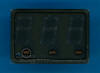
Display Layout:
| 3*SP-753 |
|
|
The Output Decoder PLA of the TMS1875NC is programmed for 7-Segment displays with the following Output Assignments:
| TMS1875 Pin | 16 | 17 | 18 | 19 | 20 | 21 | 22 | 23 | 24 |
| TMS1875 Port | SA | SB | SC | SD | SE | SF | SG | (SH) | SP |
| Segment | A | B | C | D | E | F | G | DP |
| The Segment drivers A-G and DP (Decimal Point) are connected to the Sperry SP-753 display assembly in the pictured way. Segment H is always active and not used. | 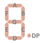 |
Display Fonts:
| Type | Calculator | Number Fonts | Decimal Separator |
Entry Overflow |
Calculating Overflow |
Minus | Segment H |
| TMS1875NC | Heathkit IC-2008 |
|
active |
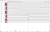
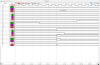
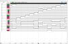 Scanning: Display and keyboard scanning is performed in D11 → D1 direction at a rate of about
584 Hz with the Digits blanked at State S1 and State S13 but no Segment
blanking:
Scanning: Display and keyboard scanning is performed in D11 → D1 direction at a rate of about
584 Hz with the Digits blanked at State S1 and State S13 but no Segment
blanking:
|
• State Time = 3 Clocks =
0.012 ms @ CK=250 kHz • Digit Time = 13 States (1 Instruction Cycle) = 0.156 ms @ CK=250 kHz • Scan Time = 11 Digit Times (D1 to D11) = 1.712 ms @ CK=250 kHz |
![]() Device-under-Test:
Device-under-Test:
| • Package Markings Top: TMS0101NC,
A7215 • Package Markings Bottom: 30038 • Donor Calculator: Heathkit IC-2008A, May 1972 |
Keyboard: The Heathkit IC-2008A makes use of a keyboard assembled with individual long-stroke push-button switches arranged in an 11*2 matrix with the rows connected to the D1-D11 Outputs (Display Scan) and the columns connected to the KN (Keyboard Scan Numerical) and KO (Keyboard Scan Operational) Inputs of the TMS0101NC single-chip calculator circuit. The thumb-wheel switch to select the position of the decimal point is connected between the D1-D7 and D10 Output and KP (Keyboard Scan Decimal Point) Input while the latching push-button switch for the Constant Mode is connected between the D10 Output and KQ (Keyboard Scan Constant) Input.
Keyboard Matrix of the Heathkit IC-2008A:
TMS0101 |
||||
| KN | KO | KP | KQ | |
| D1 | 1 | + | [F-DP1] | |
| D2 | 2 | × | [F-DP2] | |
| D3 | 3 | ÷ | [F-DP3] | |
| D4 | 4 | − | [F-DP4] | |
| D5 | 5 | [F-DP5] | ||
| D6 | 6 | [F-DP6] | ||
| D7 | 7 | +/− | [F-DP7] | |
| D8 | 8 | = | ||
| D9 | 9 | . | ||
| D10 | 0 | CE | [F-DP0] | [C-K] |
| D11 | C | |||
Display: The
Heathkit IC-2008A makes use of a 9-digit display assembly with three 3-digit
Sperry SP-753 planar neon gas discharge "Panaplex II" display modules. The
nine discrete high-voltage drivers for the Anodes of the display assembly are
connected to the D1-D8 and D11 Outputs (Display Scan) of the TMS0101NC and the 8
discrete high-voltage drivers for the Cathodes to its SA-SG and SP Outputs
(Segments) with SH not connected. An additional flip-flop with its clock input
connected to the Digit Driver output D11 of the TMS0101NC used for the left-most
digit and its two Q and /Q outputs connected to the eight discrete high-voltage
drivers. This circuitry changes the pre-programmed scanning order of the
TMS0101NC from D11→D10→D9…D1 to D11→D10→D8...D2 / D11→D9→D7…D1 (with D10 and D9
actually not used for the display of an 8-digit calculator), an implementation
of the "Interlaced Scan Multiplex Operation" recommended for multiplex operation
of SP-700 series displays. The advantage of this approach is that the blanking
time normally required within a display envelope to avoid "ghosting" is
accomplished while other display envelopes are addressed. The left-most 3-digit
Sperry SP-753 display module of the IC-2008A calculator would see a D11→D8 /
D11→D7 scanning order, the middle display module a D6→D4 / D5 scanning order,
and the right-most display module a D2 / D3→D1 scanning order, fulfilling the
150 us blanking time requirement of the SP-700 Series. The voltage swing for the
Anodes and Cathodes of the evaluated Heathkit IC-2008A calculator manufactured in
May 1972 was measured with about 80/120 Volts to 220 Volts.
Display Layout:
| 3*SP-753 |
|
|
The Output Decoder PLA of the TMS0101NC is programmed for 7-Segment displays with the following Output Assignments:
| TMS0101 Pin | 16 | 17 | 18 | 19 | 20 | 21 | 22 | 23 | 24 |
| TMS0101 Port | SA | SB | SC | SD | SE | SF | SG | SH | SP |
| Segment | A | B | C | D | E | F | G | DP |
| The Segment drivers A-G and DP (Decimal Point) are connected to the Sperry SP-753 display assembly in the pictured way. Segment H is not used. | |
Display Fonts:
| Type | Calculator | Number Fonts | Decimal Separator |
Entry Overflow |
Calculating Overflow |
Minus | Segment H |
| TMS0101NC | Heathkit IC-2008A |
|
|
off |
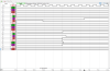
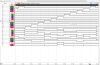
 Scanning: Display and keyboard scanning is performed in D11 → D1 direction at a rate of about
584 Hz with the Digits blanked at State S1 and State S13 but no Segment
blanking:
Scanning: Display and keyboard scanning is performed in D11 → D1 direction at a rate of about
584 Hz with the Digits blanked at State S1 and State S13 but no Segment
blanking:
|
• State Time = 3 Clocks =
0.012 ms @ CK=250 kHz • Digit Time = 13 States (1 Instruction Cycle) = 0.156 ms @ CK=250 kHz • Scan Time = 11 Digit Times (D1 to D11) = 1.712 ms @ CK=250 kHz |
![]() Device-under-Test:
Device-under-Test:
| • Package Markings Top: TMS0121NCΔ,
7319 • Package Markings Bottom: 215 184 • Donor Calculator: Olympia CD101, August 1973 |
Keyboard: The Olympia CD101 makes use of a keyboard assembled with individual long-stroke push-button switches arranged in an 11*2 matrix with the rows connected to the D1-D11 Outputs (Display Scan) and the columns connected to the KN (Keyboard Scan Numerical) and KO (Keyboard Scan Operational) Inputs of the TMS0121NC single-chip calculator circuit. The sliding switch to select the position of the decimal point is connected between the D2-D4 and D10 Output and KP (Keyboard Scan Decimal Point) Input. A diode is connected between the D10 Output and KQ (Keyboard Scan Constant) Input.
Keyboard Matrix of the Olympia CD101:
TMS0121 |
||||
| KN | KO | KP | KQ | |
| D1 | 1 | + | ||
| D2 | 2 | × | [F-DP2] | |
| D3 | 3 | ÷ | [F-DP3] | |
| D4 | 4 | − | [F-DP4] | |
| D5 | 5 | |||
| D6 | 6 | |||
| D7 | 7 | [RC] | ||
| D8 | 8 | = | ||
| D9 | 9 | . | ||
| D10 | 0 | C | [F-DP0] | [K] |
| D11 | CA | |||
![]()
![]() Display: The
Olympia CD101 makes use of an 10-digit display assembly with eleven Futaba
Vacuum Fluorescent Display (VFD) tubes mounted in a robust frame and soldered
directly to the Main printed circuit board (PCB). One Futaba SP8D2 tube is used
for the Minus sign and Overflow Indicator while ten 8-segment Futaba DG8R tubes
are used for the Numerals. The
11 discrete high-voltage drivers for the Control Grids of the display assembly are
connected to the D1-D11 Outputs (Display Scan) of the TMS0121NC and the 9
discrete high-voltage drivers for the Anodes to its SA-SH and SP Outputs
(Segments).
Display: The
Olympia CD101 makes use of an 10-digit display assembly with eleven Futaba
Vacuum Fluorescent Display (VFD) tubes mounted in a robust frame and soldered
directly to the Main printed circuit board (PCB). One Futaba SP8D2 tube is used
for the Minus sign and Overflow Indicator while ten 8-segment Futaba DG8R tubes
are used for the Numerals. The
11 discrete high-voltage drivers for the Control Grids of the display assembly are
connected to the D1-D11 Outputs (Display Scan) of the TMS0121NC and the 9
discrete high-voltage drivers for the Anodes to its SA-SH and SP Outputs
(Segments).
Display Layout:
| 1*SP8D2 + 10*DG8R- |
|
|
The Output Decoder PLA of the TMS0121NC is programmed for 7-Segment displays with the following Output Assignments:
| TMS0121 Pin | 16 | 17 | 18 | 19 | 20 | 21 | 22 | 23 | 24 |
| TMS0121 Port | SA | SB | SC | SD | SE | SF | SG | SH | SP |
| Segment | A | B | C | D | E | F | G | H | DP |
| The Segment drivers A-H and DP (Decimal Point) are connected to the Futaba SP8D2/DG8R display assembly in the pictured way. |  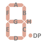 |
Display Fonts:
| Type | Calculator | Number Fonts | Decimal Separator |
Entry Overflow |
Calculating Overflow |
Minus | Segment H |
| TMS0121NC | Olympia CD101 |
|
|
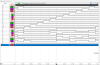
 Scanning: Display and keyboard scanning is performed in D11 → D1 direction at a rate of about
584 Hz with the Digits blanked at State S1 and State S13 but no Segment
blanking:
Scanning: Display and keyboard scanning is performed in D11 → D1 direction at a rate of about
584 Hz with the Digits blanked at State S1 and State S13 but no Segment
blanking:
|
• State Time = 3 Clocks =
0.012 ms @ CK=250 kHz • Digit Time = 13 States (1 Instruction Cycle) = 0.156 ms @ CK=250 kHz • Scan Time = 11 Digit Times (D1 to D11) = 1.712 ms @ CK=250 kHz |
If you have additions to the above article please email: joerg@datamath.org.
© Joerg Woerner, March 18, 2023. No reprints without written permission.