DATAMATH CALCULATOR MUSEUM
|
DATAMATH CALCULATOR MUSEUM |
Texas Instruments announced on September 17, 1971 with the TMS1802NC the first available standard calculator building block on a chip, it was later renamed into TMS0102. The chip integrates 3,520 Bits Read-Only program Memory (ROM, 320 Words x 11 Bits), a 182-bit Serial-Access Memory (SAM, 3 Registers * 13 Digits, 2 * 13 Bit-Flags) and a decimal arithmetic logic unit as well as control, timing, and output decoders but no drivers for the display. These function blocks of the chip add up to an overall complexity of roughly 5,000 transistors.
Due to a flexible design concept of the TMS0100 architecture with both programmable PLA and ROM techniques a lot of design variations appeared. These include two different types of the key-matrix, 8 or 10 digits of 7- or 8-segmented outputs. The polarity of the segment output can be programmed. Some displays such as LCD (Liquid-Crystal-Display) are easier to interface with inverted polarity. The blanking of the segments is also programmable within limits to facilitate the interface with certain displays such as Panaplex™. Even the style of the numbers 6, 7 and 9 varied among the family members. While the TMS0100 chip itself provides up to 10 segment outputs for Nixie tube style displays, is the 28-pin package of the device limited to a maximum of 8-segmented outputs.
A typical calculator built around the TMS0100 Product Family performs the four basic functions +, −, ×, and ÷ with either Constant or Chain operation. The calculations are done on a floating decimal-point operation but the display of the results could be selected between the floating-point or a fixed-point format. The keyboard scanning, debouncing and encoding in performed inside the chip. The display outputs are fully decoded with a leading-zero suppression and multiplexed. The TMS0120 could be called the first single-chip scientific calculator circuit, it uses in the SR-10 "slide Rule" calculator SR-10 "Slide Rule" calculator a novel approach to add to the 8-digit Mantissa in scientific notation a 2-digit Exponent and repurposing the unused Segment H for the minus sign of the Exponent.
The TMS1875 is based on the TMS1802 but uses a modified leading-zero suppression to output "half-zeros" instead of blanking the corresponding digits, enabling the use of early SP-700 Series planar neon gas discharge displays. With the TMS1875 like all members of the TMS0100 Product Family scanning the display from the left-most D11 position towards the right-most D1 position, one would expect that the corresponding digit is simply blanked to suppress it. But with the D11…D1 outputs scanning not only the display but the keyboard matrix, too, Texas Instruments needed to implement leading-zero suppression in a different way and chose to accomplish the desired functionality using the Segment Decoder of the calculator chip. This approach allowed with a very simple modification of the 7-Segment Dekoder PLA activating the segment outputs C, D, E, and G for "suppressed zeros" to output a "half-zero" instead.
Although the TMS1875 is based on the TMS1802, does it not fit into Texas Instruments' definition of the TMS0100 Product Family due to the disable leading-zero suppression.
| Type | Calculators | Keyboard | Constant (M/D) |
Digits | Fixed DP | Rounding | Special Functions |
Seg./Dig. Blanking |
(6,7,9) Font |
Seg. H | Entry Overflow |
Calculating Overflow |
Pref. Type |
| TMS1875 | Heathkit IC-2008 | [+][-][=] | 1/2 | 8 | 0-7, F | DOWN | NONE S1, S13 |
active | |||||
| TMS0101 Reference |
Heathkit IC-2008A | [+][-][=] | 1/2 | 8 | 0-7, F | DOWN | NONE S1, S13 |
YES |
| Description | Comments | |
| Architecture | Single-chip Calculator | First Generation |
| Category | Register Processor | BCD-serial |
| Related | TMS0100 | Leading-zero Suppression |
| ROM Size | 3,520 Bits | 320 Words * 11 Bits |
| RAM Size | 182 Bits | 3 Registers * 13 Digits, 2 * 13 Bit-Flags |
| Outputs | 11 Digits 9 Segments |
External Digit Drivers External Segment Drivers |
| Inputs | 4 Keyboard 0 Miscellaneous |
Digit to Keyboard Scan-Matrix |
The Datamath Calculator Museum DCM-50A (Platform) supports the TMS0100 Product Family with its left-most TMS0100 Textool Test Socket set to DCM-50A (TMS0100) mode. Both Characterization of TMS0100 Calculator Circuits and Reverse-engineering of TMS0100 Calculator Circuits is supported by the DCM-50A (TMS0100).
| Parameter | Min | Typ | Max | Unit | Comments |
| VSS | 0 | V | |||
| VDD | -8.1 | -7.2 | -6.6 | V | |
| VGG | -16.2 | -14.4 | -13.2 | V | |
| IDD | 17 | 25 | mA | ||
| IGG | 10 | 15 | mA | ||
| CK | 100 | 250 | 400 | kHz | Level between VSS and VGG |
The TMS1875 was manufactured in a 10 um metal gate PMOS process (metal width = 0.40 mil / 10 um, metal spacing = 0.40 mil / 10 um, diffusion width = 0.40 mil / 10 um, diffusion spacing = 0.4 mil / 10 um).
The die size of the TMS1875 is approximately 230 mils * 230 mils / 5.9 mm * 5.8 mm.
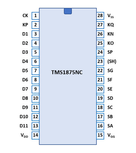
The TMS1875 uses a standard 0.6” wide 28-pin DIP (Dual In-line Package with a 0.1” / 2.54 mm lead pitch).
| Pin | IO | Function | Pin | IO | Function |
| 1 | I | Clock Input | 28 | V | Common Voltage |
| 2 | I | Keymatrix input P | 27 | I | Keymatrix input Q |
| 3 | O | Digit driver 1 (LSD) | 26 | I | Keymatrix input N |
| 4 | O | Digit driver 2 | 25 | I | Keymatrix input O |
| 5 | O | Digit driver 3 | 24 | O | Segment driver DP |
| 6 | O | Digit driver 4 | 23 | O | (Segment driver H) |
| 7 | O | Digit driver 5 | 22 | O | Segment driver G |
| 8 | O | Digit driver 6 | 21 | O | Segment driver F |
| 9 | O | Digit driver 7 | 20 | O | Segment driver E |
| 10 | O | Digit driver 8 (MSD8) | 19 | O | Segment driver D |
| 11 | O | Digit driver 9 | 18 | O | Segment driver C |
| 12 | O | Digit driver 10 (MSD10) | 17 | O | Segment driver B |
| 13 | O | Digit driver 11 (OVER) | 16 | O | Segment driver A |
| 14 | V | Negative Voltage VDD | 15 | V | Negative Voltage VGG |
| The Segment drivers A-G and DP (Decimal Point) are connected to the display in the pictured way. Segment H is always active and not used. | 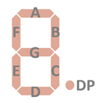 |
The keyboards of the TMS1875 and all calculators based on the TMS0100 Product Family consist of a x/y-matrix connected to the digit driver outputs D1-D11 and the keymatrix inputs KN (Numbers) and KO (Operations). In the fixed-point output format mode the position of the decimal point is selected with the KP (Decimal Point) input. The Constant/Chain switch is connected between D10-KQ (Constant).
Scanning is performed in D11 → D1 direction at a rate of about 584 Hz:
|
• State Time = 3 Clocks =
0.012 ms @ CK=250 kHz • Digit Time = 13 States (1 Instruction Cycle) = 0.156 ms @ CK=250 kHz • Scan Time = 11 Digit Times (D1 to D11) = 1.712 ms @ CK=250 kHz |
TMS1875 |
TMS0101 (Reference) |
||||||||
| KN | KO | KP | KQ | KN | KO | KP | KQ | ||
| D1 | 1 | + | DP1 | D1 | 1 | + | DP1 | ||
| D2 | 2 | × | DP2 | D2 | 2 | × | DP2 | ||
| D3 | 3 | ÷ | DP3 | D3 | 3 | ÷ | DP3 | ||
| D4 | 4 | − | DP4 | D4 | 4 | − | DP4 | ||
| D5 | 5 | DP5 | D5 | 5 | DP5 | ||||
| D6 | 6 | DP6 | D6 | 6 | DP6 | ||||
| D7 | 7 | +/− | DP7 | D7 | 7 | +/− | DP7 | ||
| D8 | 8 | = | D8 | 8 | = | ||||
| D9 | 9 | . | D9 | 9 | . | ||||
| D10 | 0 | CE | DP0 | K | D10 | 0 | CE | DP0 | K |
| D11 | C | D11 | C | ||||||
Calculators based on the TMS1875 use planar neon gas discharge Sperry SP-753 "Panaplex™ II" display modules .
If you have additions to the above datasheet please email: joerg@datamath.org.
© Joerg Woerner, March 18, 2023. No reprints
without written permission.