DATAMATH CALCULATOR MUSEUM
|
DATAMATH CALCULATOR MUSEUM |
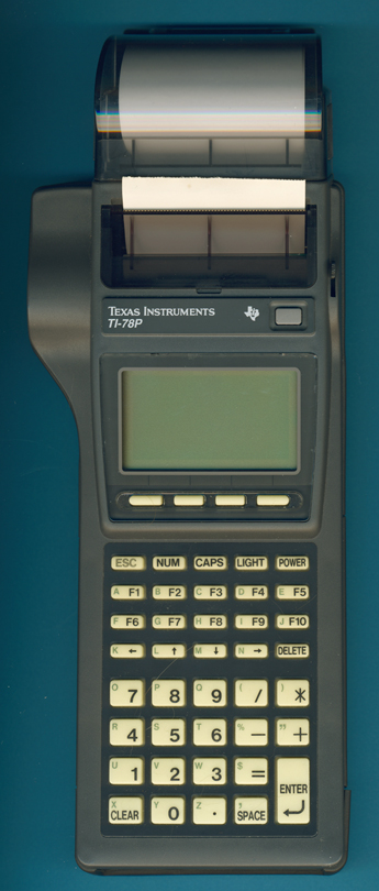
Texas Instruments TI-78P (Prototype)
| Date of introduction: | Never (Announced: 1990) |
Display technology: | LCD dot matrix |
| New price: | Display size: | 8 * 20 characters | |
| Size: | 10.2" x 4.1" x
1.6" 260 x 105 x 41 mm3 |
||
| Weight: | 23 ounces, 657 grams | Serial No: | T002 |
| Batteries: | BP-78 (4.8V NiCd, 480mAh) + CR2025 | Date of manufacture: | mth 08 year 1989 |
| AC-Adapter: | none | Origin of manufacture: | Japan |
| Precision: | Integrated circuits: | CPU: OKI M80C88A ASIC:TC17G080A ROM: TC57512A RAM: 24*CM5M5256 RTC: HD146818A Display: T9842B, T9841B |
|
| Memories: | 768kB RAM, 64kB ROM | ||
| Program steps: | Courtesy of: | Joerg Woerner |
![]()
 Well,
before we discuss this unique TI-78P Prototype in detail, we need to understand
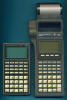
the TI-78 first. Featuring both devices side by side on
the picture to the right, we start with the TI-78: Does
this TI-78 look like an electronic calculator? At first glance you'll
notice a numeric keyboard, a multiline display, some promising function-keys but
you miss probably all the scientific or financial functions. With a second view you'll
probably snatch the alphanumeric overlay of the keyboard and an unusual display
with the headline "LOAD MONITOR".
Well,
before we discuss this unique TI-78P Prototype in detail, we need to understand
the TI-78 first. Featuring both devices side by side on
the picture to the right, we start with the TI-78: Does
this TI-78 look like an electronic calculator? At first glance you'll
notice a numeric keyboard, a multiline display, some promising function-keys but
you miss probably all the scientific or financial functions. With a second view you'll
probably snatch the alphanumeric overlay of the keyboard and an unusual display
with the headline "LOAD MONITOR".
Meditating about the "TI-78" type designation places this odd machine somewhere between the TI-74 BASICALC introduced in 1986 and the failed TI-88 scheduled for release in 1982. If we focus on the style of lettering and the place of the logo, we recognize the famous TI-81, introduced in 1990.
And we are right, the TI-78 was introduced in 1990 and continues a tradition started with the TI-59 and carried forward with the TI-88 and TI-74 BASICALC: "Customized calculators", the evolution of "Programmable calculators".
If you sketch the block diagram of a calculator, you are actually drawing a basic computer system running one permanent program:
|
• INPUT: Keyboard • PROCESSING: Mask-programmed processing unit • OUTPUT: Display |
Texas Instruments created for the SR-50 a flexible microcomputer architecture for scalable scientific calculators. Just adding one additional mask-programmed ROM (Read-Only Memory) to the SR-50 and the result was the SR-51 with enhanced statistical functions. Adding one additional RAM as program memory to the design and we have the SR-56. Main disadvantage of these keyboard programmable calculators was the volatile program memory. With the later TI-58 a total of 480 program steps took about 2 hours to be entered with the tiny keyboard. And if your battery was weak the remaining operating time was some 30 minutes.
The legendary TI-59 - we celebrated on May 24, 2007 its 30th Anniversary - overcame this problem with a card reader for magnetic strips. But the real revolution of the TI-59 was hidden by a small lid on the backside of the calculator, the Solid State Software Modules™ with up to 5000 program steps. Dozens of companies used this module concept for innovative, customized solutions like the Allianz Insurance calculator, the Bossard Screw calculator or the USMC Harrier Flight computer.
The never released TI-88 even included two slots on its rear side to accommodate CRAM and CROM Modules and allowed with an alphanumerical display and its [YES], [NO], and [UNKNOWN]-keys smart dialogs.
With the TI-74 BASICALC the inconvenient "keyboard code programming" was replaced with the more sophisticated BASIC program language. Once again used Texas Instruments RAM- and ROM-cartridges for this flexible computer system to enhance its capabilities. The almost identical TI-74S was dedicated to OEM applications and found dozens of applications with assurance and insurance companies.
And where is the slot of the TI-78 you may ask? To be honest, it is invisible! The TI-78 went one step further and integrated an Infrared Communication port, capable of 38,400 bits per second serial communication with a Personal Computer (PC).
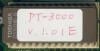
TI-78P - Texas Instruments 78 Printer. That was easy! Maybe too easy.
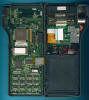
![]() Dismantling
this TI-78P Prototype manufactured in August 1989 in Japan by (most likely)
Toshiba reveals a very organized design utilizing both shells of the housing
perfectly:
Dismantling
this TI-78P Prototype manufactured in August 1989 in Japan by (most likely)
Toshiba reveals a very organized design utilizing both shells of the housing
perfectly:
|
• INPUT: Keyboard (top shell) • PROCESSING: CPU, RAM, ROM etc. (bottom shell) • OUTPUT: Display, Printer (top shell) • POWER: Lithium battery (top shell) |
Both the keyboard and backlight illuminated display seem to be
identical with the released TI-78 while the printer might be a generic OEM
product. The battery used in this TI-78P is most likely identical with the BP-78
from the TI-78 but doesn't sport any specifications on the housing. The
processing unit of this TI-78P Prototype sports like the later TI-78 a well known computer architecture
but is obviously not as polished as the final product.
It is very similar
to the early PC (Personal Computer) and centered around an Intel 8088 compatible microprocessor manufactured in power-saving CMOS technology by OKI.
The large and complex printed circuit board (PCB) located in the bottom shell of
this TI-78P Prototype makes use of six main components plus the battery:
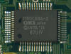 CPU (Central Processing Unit): OKI Semiconductor, now a
subsidiary of ROHM, introduced with the M80C88A an officially licensed variant
of Intel's 8088 microprocessor using a low-power CMOS process. The -2 marking on
its QFP (Quad Flat Package) indicates a maximum speed of 8 MHz.
CPU (Central Processing Unit): OKI Semiconductor, now a
subsidiary of ROHM, introduced with the M80C88A an officially licensed variant
of Intel's 8088 microprocessor using a low-power CMOS process. The -2 marking on
its QFP (Quad Flat Package) indicates a maximum speed of 8 MHz.
 ROM (Read-Only Memory): ROM
is used in computers and other electronic devices to store operating systems,
programs and constant data. In mask ROM, the data is physically encoded in the
circuit, so it can only be programmed during fabrication. While mask ROM are
very economical in large quantities, there are some major disadvantages
associated with the technology: The turnaround time between completing the data
set for a mask ROM and receiving the finished product is long and bugs lead to a
long cycle time.
ROM (Read-Only Memory): ROM
is used in computers and other electronic devices to store operating systems,
programs and constant data. In mask ROM, the data is physically encoded in the
circuit, so it can only be programmed during fabrication. While mask ROM are
very economical in large quantities, there are some major disadvantages
associated with the technology: The turnaround time between completing the data
set for a mask ROM and receiving the finished product is long and bugs lead to a
long cycle time.
 Subsequent developments addressed these problems and the
invention of EPROM, or Erasable Programmable Read-Only Memory, solved the
problems, because the memory contend can be reset by exposure the silicon chip
through a glass window in the housing to strong UV light. The same EPROM chip
packaged into an opaque housing, results in the OTP-ROM, or One-time
Programmable Read-Only Memory, a technology usually used for quick production
ramp-up at higher costs. The development of the Flash Memory, a specific type of
EEPROM (Electrically Erasable Programmable Read-Only Memory), allows changes in
the programs or data on the fly and replaced mask ROM in most applications.
Subsequent developments addressed these problems and the
invention of EPROM, or Erasable Programmable Read-Only Memory, solved the
problems, because the memory contend can be reset by exposure the silicon chip
through a glass window in the housing to strong UV light. The same EPROM chip
packaged into an opaque housing, results in the OTP-ROM, or One-time
Programmable Read-Only Memory, a technology usually used for quick production
ramp-up at higher costs. The development of the Flash Memory, a specific type of
EEPROM (Electrically Erasable Programmable Read-Only Memory), allows changes in
the programs or data on the fly and replaced mask ROM in most applications.
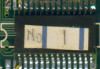
The
prominent Toshiba TC57512A chip mounted in a white socket is actually an EPROM
with a capacity of 64k Bytes and manufactured in a mix of CMOS and NMOS
technology to achieve a low-power consumption of only 30 mA. It took us by
surprise to locate a second ROM on the Main-PCB, labeled on the silkscreen with
TC534, a mask ROM device with a massive of 512k Bytes capacity in a tiny 32-pin
package. The PCB itself is populated with an unidentified memory chip with a
28-pin package and obviously the Vcc line (and /OE line) connected with hand
soldered yellow wires. Looking into data sheets of various memory devices we
suspect an OTP-ROM with 32k Bytes capacity.
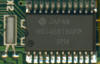
![]() RAM (Random Access Memory): The RAM is used as data memory and is used to store both variables, user programs and intermediate results. This
TI-78P Prototype makes use of 24 M5M5256B S-RAM (Static RAM) chips manufactured by Mitsubishi, Japan with
32k Bytes
capacity, each. There are actually two different memory chips populated in pairs
on the PCB, labeled M5M5256BVP 12L resp. M5M5256BRV 12L. Both devices use the
same silicon rated for an access time of 120 ns and selected for low-power
standby consumption of only 20 uA, but mounted in different orientation into the
package for an easy design of the PCB. The total capacity of with the 24 memory
chips populated on both sides of the PCB amounts to 768k Bytes.
RAM (Random Access Memory): The RAM is used as data memory and is used to store both variables, user programs and intermediate results. This
TI-78P Prototype makes use of 24 M5M5256B S-RAM (Static RAM) chips manufactured by Mitsubishi, Japan with
32k Bytes
capacity, each. There are actually two different memory chips populated in pairs
on the PCB, labeled M5M5256BVP 12L resp. M5M5256BRV 12L. Both devices use the
same silicon rated for an access time of 120 ns and selected for low-power
standby consumption of only 20 uA, but mounted in different orientation into the
package for an easy design of the PCB. The total capacity of with the 24 memory
chips populated on both sides of the PCB amounts to 768k Bytes.
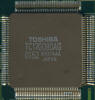 ASIC: A Toshiba TC17G080 ASIC forms the Glue-logic of the design and
connects the peripherals (Keyboard, Printer, Display, Communication Ports) to the
processing unit. The TC17G ASIC family was manufactured in a 2um C-MOS process
and featured complexities between 540 and 10,000 gates.
ASIC: A Toshiba TC17G080 ASIC forms the Glue-logic of the design and
connects the peripherals (Keyboard, Printer, Display, Communication Ports) to the
processing unit. The TC17G ASIC family was manufactured in a 2um C-MOS process
and featured complexities between 540 and 10,000 gates.
 RTC (Real Time Clock): This TI-78P Prototype makes use
of a HD146818A RTC manufactured by Hitachi and combining a time-of-day clock
with alarm, 100-year calendar with leap year correction and 50 bytes of RAM in a
compact 24-pin package.
RTC (Real Time Clock): This TI-78P Prototype makes use
of a HD146818A RTC manufactured by Hitachi and combining a time-of-day clock
with alarm, 100-year calendar with leap year correction and 50 bytes of RAM in a
compact 24-pin package.
DISPLAY: The
dot matrix display of the TI-78P Prototype features 64 * 120 pixels and to
display up to 8 lines of 20 characters, each. The Toshiba T9842B
Display controller drives the rows of the display, the columns are connected to
its T9841B counter part. We know a similar display from the first TI-81
introduced in 1990.
The [LIGHT]-key of the TI-78P activates the backlight illumination and enhances
the contrast of the LC-Display slightly.
 POWER: The TI-78P Prototype is powered by a slim, rechargeable battery pack. We
assume an operation time of 10 hours based on the estimated (from the released
TI-78) 400 mAh capacity and the
internal construction. The S-RAMs maintain program and data even if the TI-78P is
switched off due to a power saving standby function and an additional CR2025
Lithium battery.
POWER: The TI-78P Prototype is powered by a slim, rechargeable battery pack. We
assume an operation time of 10 hours based on the estimated (from the released
TI-78) 400 mAh capacity and the
internal construction. The S-RAMs maintain program and data even if the TI-78P is
switched off due to a power saving standby function and an additional CR2025
Lithium battery.
Writing an application program for the TI-78P requires a complete development
system based on a DOS 5.0 or DOS 6.0 Personal Computer and a Microsoft C
compiler. There are a lot of ideas for such a "Programmable Data
Terminal" like inventory control, mail delivery management and more. But
even in 1990 there was a lot of competition in this market from mainly Japanese
companies.
TI-78? Read more about Chinese Lucky Numbers.
If you have additions to the above article please email: joerg@datamath.org.
© Joerg Woerner, October 30, 2019. No reprints without written permission.