DATAMATH CALCULATOR MUSEUM
|
DATAMATH CALCULATOR MUSEUM |
American Microsystems, Inc (AMI) introduced in Fall 1973 with the S2144 a single-chip calculator circuit for portable, battery-operated calculators. With no "Datasheets" of the S2144 available, we reverse-engineered both Melcor Model 1000 and RFT minirex 74 calculators to provide the relevant information for the calculator enthusiasts.
A typical calculator built around the AMI S2144 performs the four basic functions +, −, ×, and ÷ and allows to select between the floating-point or a fixed-point format. The S2144 supports additionally a power-safe mode turning the display off (sans the "minus sign" in the right-most digit) while still scanning the keyboard and holding calculating results. One additional input of the S2144 can be used to monitor the battery voltage and indicate with a "decimal point" in the left-most digit a low-battery status. The keyboard scanning, debouncing and encoding in performed inside the chip. The display outputs are fully decoded with a leading zero suppression and multiplexed.
| Type | Calculators | Keyboard | Constant | Digits | Fixed DP | Rounding | Seg./Dig. Blanking |
(6,7,9) Font |
Entry Overflow |
Calculating Overflow |
Low Voltage |
| S2144 | Melcor Model 1000, RFT minirex 74 | [+][−][=] | n.a. | 8 | F, 0-7 | None | S1, S8 NONE |
|
|
The Datamath Calculator Museum DCM-50A (Platform) supports the AMI S2144 directly with the TMS1000 Textool Test Socket set to DCM-50A (TMS1000) mode and patching (swapping) most of the pins. One additional patch wire is needed to connect the external clock oscillator not available on the TMS1000 Socket but on the TMS0100 Socket or directly through the Digilent Digital Discovery Interface. Both Characterization of TMS1000 Calculator Circuits and Reverse-engineering of TMS1000 Calculator Circuits is supported by the DCM-50A (TMS1000).
| Item | Min | Typ | Max | Unit | Comments |
| VSS | 0 | V | |||
| VDD | -6.2 -6.6 |
V V |
(Melcor Model 1000) (RFT minirex 74) |
||
| VGG | -10.0 -11.0 |
V V |
(Melcor Model 1000) (RFT minirex 74) |
||
| IDD | 9.0 | mA | (Melcor Model 1000) | ||
| IGG | 3.0 | mA | (Melcor Model 1000) | ||
| CK | 35 40 |
kHz kHz |
(Melcor Model 1000) (RFT minirex 74) |
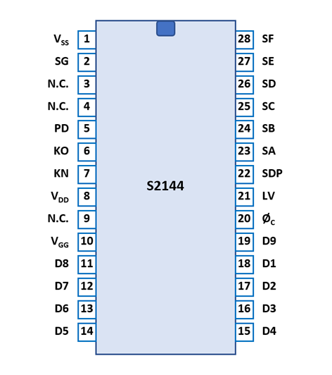
The S2144 uses a 0.6” wide 28-pin CDIP (Ceramic Dual In-line Package with a 0.1” / 2.54 mm lead pitch).
| Pin | IO | Function | Pin | IO | Function |
| 1 | V | Common Voltage | 28 | V | Segment driver F |
| 2 | O | Segment driver G | 27 | O | Segment driver E |
| 3 | Do not connect | 26 | O | Segment driver D | |
| 4 | Do not connect | 25 | O | Segment driver C | |
| 5 | I | Power Down | 24 | O | Segment driver B |
| 6 | I | Keymatrix input O | 23 | O | Segment driver A |
| 7 | I | Keymatrix input N | 22 | O | Segment driver DP |
| 8 | V | Negative Voltage VDD | 21 | I | Low Voltage |
| 9 | Do not connect | 20 | I | Clock Input | |
| 10 | V | Negative Voltage VGG | 19 | O | Digit driver 9 (OVER) |
| 11 | O | Digit driver 8 (MSD) | 18 | O | Digit driver 1 (LSD) |
| 12 | O | Digit driver 7 | 17 | O | Digit driver 2 |
| 13 | O | Digit driver 6 | 16 | O | Digit driver 3 |
| 14 | O | Digit driver 5 | 15 | O | Digit driver 4 |
| The Segment drivers A-G and the Decimal point are connected to a display in the pictured way. | 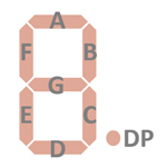 |
The keyboards of all calculators based on the S2144 consists of a x/y-matrix connected to the digit driver outputs D1-D9 and the keymatrix inputs KN and KO. In the fixed-point output format mode the position of the decimal point is selected with the PD key.
Example for the Melcor Model 1000:
| KN | KO | |
| D1 | 1 | × |
| D2 | 2 | ÷ |
| D3 | 3 | PD |
| D4 | 4 | + |
| D5 | 5 | − |
| D6 | 6 | = |
| D7 | 7 | C/CE |
| D8 | 8 | 0 |
| D9 | 9 | . |
Calculators based on the AMI2144 use normally LED displays. Texas Instruments introduced together with their calculator chips two pre-configured LED-modules (DIS40, DIS95) based on the TIL360 arrays, the corresponding segment drivers (SN75491) and digit drivers (SN75492). Many designs make use of these or similar components.
If you have additions to the above datasheet please email: joerg@datamath.org.
© Joerg Woerner, February 05, 2023. No reprints
without written permission.