DATAMATH CALCULATOR MUSEUM
|
DATAMATH CALCULATOR MUSEUM |
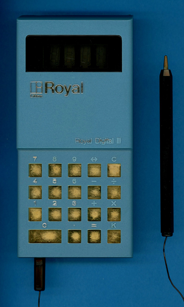
Litton Royal Digital III
| Date of introduction: | November 20, 1971 | Display technology: | Fluorescent |
| New price: | Display size: | 4 | |
| Size: | 6.1" x 3.2" x 1.4" 156 x 82 x 36 mm3 |
||
| Weight: | 12.8 ounces, 364 grams | Serial No: 046684 | H023231 |
| Batteries: | 6*AA NiCd | Date of manufacture: | mth 12 year 1971 |
| AC-Adapter: | Origin of manufacture: | USA | |
| Precision: | 8 | Integrated circuits: | General Instrument 250 |
| Logic: | Chain | Displays: | |
| Memories: | |||
| Program steps: | Courtesy of: | Joerg Woerner |
![]() Litton Industries,
headquartered in Beverly Hills, California, acquired in 1958
Monroe Calculating Machine Company, an American manufacturer of mechanical calculators.
In 1966 Litton acquired Imperial Typewriter Company Ltd, a very successful manufacturer of typewriters and merged it with its own
Royal Typewriter division. In 1969
the conglomerate was further growing with the acquisition of
Triumph-Adler, the merger of UK Triumph Cycle Company and Adler, a German
manufacturer of bicycles, typewriters, sewing machines and calculators. Early
in the 1970s, Litton sold, depending on the region, electronic calculators under
five different brands: Adler, Imperial, Monroe, Royal and Triumph.
Litton Industries,
headquartered in Beverly Hills, California, acquired in 1958
Monroe Calculating Machine Company, an American manufacturer of mechanical calculators.
In 1966 Litton acquired Imperial Typewriter Company Ltd, a very successful manufacturer of typewriters and merged it with its own
Royal Typewriter division. In 1969
the conglomerate was further growing with the acquisition of
Triumph-Adler, the merger of UK Triumph Cycle Company and Adler, a German
manufacturer of bicycles, typewriters, sewing machines and calculators. Early
in the 1970s, Litton sold, depending on the region, electronic calculators under
five different brands: Adler, Imperial, Monroe, Royal and Triumph.
When Pico Electronics Ltd. of Glenrothes, Scotland was formed in 1970 by four former General Instrument (GI) engineers to realize their vision of a "single-chip calculator circuit" that they couldn’t pitch successfully to their former managers. It was no other than the CEO of GI providing the Pico Electronics team with startup capital under an extremely smart deal: If the design idea works out as envisioned, Pico Electronics would grant General Instrument the exclusive rights to manufacture and sell the chips on a global base. Their first customer was Litton Industries, introducing in November 1971 one of the first battery powered handheld calculators. Pico Electronics put during the design of their first single-chip calculator circuit, internally simply called PICO1, a lot of efforts into reducing both the cost of the calculator chip and the calculator itself:
| • Small size of the silicon chip
(die) • Low pin count of the chip package • Avoiding a grid-based keyboard matrix to allow for cost-effective calculator keyboards • Outputting 8-digit calculating results in two groups of four digits to reduce the cost of the calculator display |
The manufacturing costs of an Integrated Circuit (IC) are calculated with:
|
• IC cost = (Die cost + Testing cost + Packaging cost) / Final test yield |
With the die cost roughly proportional to the die area, testing and packaging costs roughly proportional to the pin count, and the final test yield mostly inverse proportional to the die area, goals are well defined: Keep the die size as small as possible for a set of requirements agreed on. With both ROM (Read-Only Memory) and shift-register based data memory (SAM, Serial-Access Memory) sizes the main contributors to the die area, Pico Electronics made some interesting design choices with the development of the PICO1 chip, both with the user interface and the embedded calculating logic, but certainly with the implementation of the calculator circuit. Litton Industries made with the Royal Digital III use of Pico Electronics' "cost-down" approach and was dropping the mechanical key switches known from their competitors in favor of a simple stylus and gold-plated keyboard contacts etched directly on the printed circuit board (PCB) of the calculator. Together with its bulky housing and the 4-digit display certainly not the best ingredients for a successful launch. Litton Industries learned their lessons and introduced in a first step the Digital IV featuring an 8-digit LED display and with the Digital V an 8-digit Vacuum Fluorescent Display (VFD) and a keyboard with tactile switches.
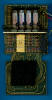
 Dismantling
the featured Litton Royal Digital III calculator manufactured in December 1971
in the United States
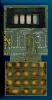
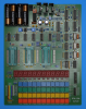
reveals a rather complex design based on three double-sided PCBs for the main electronics, the
display module, the power supply module and powered
by six internal rechargeable NiCd batteries or an external power adapter. The
three PCBs are using high-quality connectors for their various interconnections
and all electronic components are from highest quality standards.
Dismantling
the featured Litton Royal Digital III calculator manufactured in December 1971
in the United States
reveals a rather complex design based on three double-sided PCBs for the main electronics, the
display module, the power supply module and powered
by six internal rechargeable NiCd batteries or an external power adapter. The
three PCBs are using high-quality connectors for their various interconnections
and all electronic components are from highest quality standards.
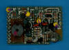
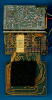 The
Main-PCB is centered around a General Instrument 250
single-chip calculator circuit and the other remaining
components on the PCB are mainly used for the keyboard interface with two
resistors for each of the 19 contacts and a transistor for for stylus. The Power
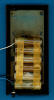
Supply and Clock Module mounted on top of the Display Module generates the different supply voltages
for the GI 250 and the Vacuum Fluorescent Display (VFD) while the Display-Module
used just four additional transistors for the grids of the display.
The
Main-PCB is centered around a General Instrument 250
single-chip calculator circuit and the other remaining
components on the PCB are mainly used for the keyboard interface with two
resistors for each of the 19 contacts and a transistor for for stylus. The Power
Supply and Clock Module mounted on top of the Display Module generates the different supply voltages
for the GI 250 and the Vacuum Fluorescent Display (VFD) while the Display-Module
used just four additional transistors for the grids of the display.
![]()
![]()
 To gain some knowledge about the differences
between the GI 250 located in this Litton Royal Digital III and the GI 251F used
with the Royal Digital V, we decided here at the Datamath Calculator Museum to
acquire a second unit of the rare Digital III calculator (Serial Number H845597, manufactured in March 1972) and give
it a full "Teardown Treatment", sharing our findings accordingly.
To gain some knowledge about the differences
between the GI 250 located in this Litton Royal Digital III and the GI 251F used
with the Royal Digital V, we decided here at the Datamath Calculator Museum to
acquire a second unit of the rare Digital III calculator (Serial Number H845597, manufactured in March 1972) and give
it a full "Teardown Treatment", sharing our findings accordingly.
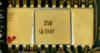 Calculating Unit:
The GI 250 used with the Litton Royal Digital III is the first implementation of
the PICO1 single-chip calculator - on the silicon die labeled as E 1971 PICO1 76250:
Calculating Unit:
The GI 250 used with the Litton Royal Digital III is the first implementation of
the PICO1 single-chip calculator - on the silicon die labeled as E 1971 PICO1 76250:
| • E - Mask Revision E • 1971 - Copyright of the PICO1 Chip, First silicon June 1971 • PICO1 - Internal product designation of Pico Electronics • 76250 - Internal product designation of General Instrument |
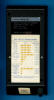
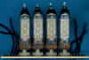 Display:
The "Teardown" Litton Royal Digital III calculator manufactured
in March 1972 makes use of four low-voltage VFD tubes manufactured by an unknown
company and soldered with their pins directly to the
Display-PCB.
Display:
The "Teardown" Litton Royal Digital III calculator manufactured
in March 1972 makes use of four low-voltage VFD tubes manufactured by an unknown
company and soldered with their pins directly to the
Display-PCB.
Display Driver: With early "low-voltage" Vacuum Fluorescent Displays
usually operated between 30 Volts and 45 Volts, significantly higher than the operating
voltage of single-chip calculator circuits, did we expect to locate some
discrete or integrated display drivers on the PCBs of the "Teardown" Litton
Royal Digital III calculator. To our surprise is the calculator electronics
using only four discrete transistors to drive the grids of the VFD tubes while
the segments of the VFD tubes are connected directly to the output pins of the
GI 250 chip. Measuring the supply voltage of the GI 250 chip results in a rather
high value of 25 Volts while the VFD tubes operate with a rather low voltage of
only 29 Volts - still within the specification of the GI 250 output drivers.
Clock: The Power Supply and Clock Module of the Litton Royal Digital III
is providing the clock signal for the GI 250 Chip with a frequency of about 100
to 125 kHz.
 Power Supply: The Litton Royal Digital III calculator is powered with
six internal, AA-sized rechargeable batteries or an external 7.2 Volt power adapter and uses a
complex DC/DC converter to
generate a total of four voltages:
Power Supply: The Litton Royal Digital III calculator is powered with
six internal, AA-sized rechargeable batteries or an external 7.2 Volt power adapter and uses a
complex DC/DC converter to
generate a total of four voltages:
|
• VSS - Positive supply for
GI 250 (+5.0 V) • VDD - Negative supply for GI 250 (-20.0 V) • VPP - Negative supply for VFD anodes and grids (-24.0 V) • VFIL - AC supply for VFD Filament (2.5 V) |
We measured the operating current of the featured Litton Royal Digital III calculator for two different cases:
| Mode | Display | Current VBAT = 7.5 V |
Clock Frequency |
| Calculating | 0000 | 158 mA | 97 kHz |
| Calculating | 8888. | 161 mA | 97 kHz |
Calculating the power consumption at 7.5 Volts for the Litton Royal Digital III results in about 1,190 mW displaying a '0000' and about 1,210 mW with all segments illuminated.
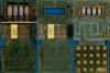
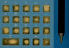 Keyboard:
The keyboard of the Litton Royal Digital III calculator uses 19 gold-plated
squares/rectangles etched on its Main-PCB and a wired stylus with a metal tip to
operate the calculator. With Integrated Circuits in PMOS (p-channel Metal–oxide Semiconductor) technology
being one of the most electrostatic-sensitive devices in electronics, a very
interesting approach. With the keypad openings of the calculator large enough to
touch the contacts with your finger, both Pico Electronics and Litton Royal
provided some measures to reduce the risk of failures of the GI 250 Chip.
Richard from Richi's Lab in Germany noticed while reverse-engineering the
related C-500 Chip that its layout is including some additional features to
improve the robustness with respect to electrostatic discharges. Looking closely
into the layout of the Main-PCB of the "Teardown" calculator reveals 19
additional resistors connected between the keypads and the C-250 Chip and even
an additional driver transistor for the stylus.
Keyboard:
The keyboard of the Litton Royal Digital III calculator uses 19 gold-plated
squares/rectangles etched on its Main-PCB and a wired stylus with a metal tip to
operate the calculator. With Integrated Circuits in PMOS (p-channel Metal–oxide Semiconductor) technology
being one of the most electrostatic-sensitive devices in electronics, a very
interesting approach. With the keypad openings of the calculator large enough to
touch the contacts with your finger, both Pico Electronics and Litton Royal
provided some measures to reduce the risk of failures of the GI 250 Chip.
Richard from Richi's Lab in Germany noticed while reverse-engineering the
related C-500 Chip that its layout is including some additional features to
improve the robustness with respect to electrostatic discharges. Looking closely
into the layout of the Main-PCB of the "Teardown" calculator reveals 19
additional resistors connected between the keypads and the C-250 Chip and even
an additional driver transistor for the stylus.
 Here
at the Datamath Calculator Museum we use
the DCM-50A Platform to
Characterize and
Reverse-engineer
Single-chip Calculator Circuits. Many designs of electronic calculators do not
use all features of their calculator brains and it would be difficult to unleash
the full potential of the calculator chips in these cases. Additionally are
electronic calculators "closed systems" with limited flexibility to measure
signals, change voltages or clock frequencies, provide additional input keys or
even change the display technology or specifications additional digits. Core
idea of the DCM-50A is providing a generic platform to access all features of a
single-chip calculator circuit and with the
DCM-50A (PLAYGROUND) we
increased the scope from Texas Instruments products to offerings from their
competitors in the 1970s, namely AMI, Cal-Tex, Commodore/MOS Technology,
Electronic Arrays, General Instrument, Hitachi, Litronix, Matsushita,
Mitsubishi, Mostek, National Semiconductor, NEC, Omron, RFT, Rockwell, Sharp,
Toshiba, and Western Digital.
Here
at the Datamath Calculator Museum we use
the DCM-50A Platform to
Characterize and
Reverse-engineer
Single-chip Calculator Circuits. Many designs of electronic calculators do not
use all features of their calculator brains and it would be difficult to unleash
the full potential of the calculator chips in these cases. Additionally are
electronic calculators "closed systems" with limited flexibility to measure
signals, change voltages or clock frequencies, provide additional input keys or
even change the display technology or specifications additional digits. Core
idea of the DCM-50A is providing a generic platform to access all features of a
single-chip calculator circuit and with the
DCM-50A (PLAYGROUND) we
increased the scope from Texas Instruments products to offerings from their
competitors in the 1970s, namely AMI, Cal-Tex, Commodore/MOS Technology,
Electronic Arrays, General Instrument, Hitachi, Litronix, Matsushita,
Mitsubishi, Mostek, National Semiconductor, NEC, Omron, RFT, Rockwell, Sharp,
Toshiba, and Western Digital.
On our quest to document Pico Electronics' PICO1 Chip and its
many descendants like the General Instrument C-500, C-550, CZ-550, C-560, C-570 and
CZL-550, we developed here at the Datamath Calculator Museum three additional
tools for our DCM-50A (PLAYGROUND):
| • DCM-50A
(PLAYGROUND) C-500
Family Adapter: Daughter Board for the
DCM-50A (PLAYGROUND)
Frame Carrier for
General Instrument's C-500 Portfolio • DCM-50A (PLAYGROUND) KBD102 Keyboard: Keyboard with 20 individual keys to support the PICO1-style keyboard reading • DCM-50A (PLAYGROUND) Digilent I/O Extender: Plug-In Board to add six additional Input Signals for the Digilent Discovery |
Comparing the Calculator Logic Implementation of the later GI 251F chip with the Calculator Logic Implementation of the GI 250 chip retrieved from the "Teardown" Litton Royal Digital III reveals no differences other than the missing toggle key.
Don't miss the "Picolator" on the German Richi's Lab site, an Emulator for General Instrument's C-550 single-chip calculator circuit - still using the PICO1 program code from the original GI 250 chip.
If you have additions to the above article please email: joerg@datamath.org.
© Joerg Woerner, July 6, 2025. No reprints without written permission.