DATAMATH CALCULATOR MUSEUM
|
DATAMATH CALCULATOR MUSEUM |
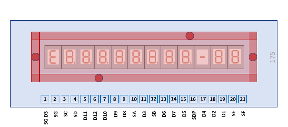
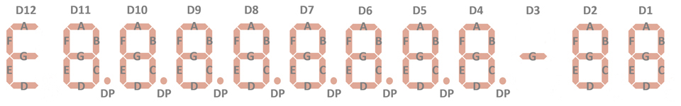
These Twelve-Digit Calculator Numeric Seven-Segment LED Displays are intended for use under pulsed conditions by enabling the common cathode of each digit sequentially and enabling the desired Segment and Decimal Point anodes in phase with the character enabling pulse. The pulse rate is kept high enough so that light from each character appears to the eye to be constant. The "G" segment of Digit 3 is accessible on a separate terminal to allow its use as the minus sign of the Exponent for scientific calculators based on the TMS0100 family of single-chip calculator circuits.
The DIS175 Twelve-Digit display assembly consists of a printed circuit board (PCB) with 12 individual, partly populated Seven-Segment displays and succeeds the DIS115F Display-PCB introduced with the SR-10 and using 12 individual DISXXX Seven-Segment displays. While the DIS175 maintains the mechanical dimensions of the DIS115F, reduces its decreased spacing between the individual display elements and the missing magnifying lens the readability of the 0.125”/3.2 mm characters slightly.
|
• 0.125”/3.2 mm Characters • Seven-Segment Digits with Right-Hand Decimals • Continuous Uniform Segments • Wide Viewing Angle • Common-Cathode Configuration for Multiplex Applications • 0.185”/4.7 mm Character Spacing • Integrated Clear Plastic Lens |
| Type | Products | Digits | Comments |
| DIS175 | Montgomery Ward P300 Version 2, Radio Shack EC-425 | Segment G Digit 3 |
| Type | Products | Relationship | Comments |
| DIS115F | SR-10 Version 1, Display 2, SR-10 Version 2, SR-10 Version 3, SR-11 Version 1, Display 2 | Predecessor | Uses 12*DISXXX |
| DIS206A | TI-2550 Version 2 | Relative | 9-Digit Bowmar Optostic |
| Item | Min | Typ | Max | Unit | Comments |
| Display Width |
2.65 67.5 |
inch mm |
|||
| Display Height |
0.87 22.0 |
inch mm |
|||
| Display Depth |
0.26 6.7 |
inch mm |
Including Printed Circuit Board, without Pins |
||
| PCB Thickness |
0.03 0.8 |
inch mm |
|||
| Lens Width |
2.50 63.5 |
inch mm |
|||
| Lens Height |
0.36 9.2 |
inch mm |
|||
| Lens Depth |
0.23 5.9 |
inch mm |
|||
| Character Height |
0.125 3.18 |
inch mm |
|||
| Character Width |
0.085 2.15 |
inch mm |
w/o Decimal Point | ||
| Character Slant Angle |
10 | degrees | |||
| Character Spacing |
0.185 4.70 |
inch mm |
The individual segment and decimal GaAsP (Gallium Arsenide Phosphide) LED chips are mounted with the substrate cathode at the desired positions on a printed circuit board (PCB) and the anodes bonded to the gold plated traces. A one-piece red acrylic plastic lens is attached to the PCB with four heat stakes providing protection for the chips.
The DIS115 uses a 2.65" / 67.5 mm by 0.87” / 22.0 mm rectangular printed circuit board (PCB) with 21 solder tabs with a 0.1” / 2.54 mm pitch arranged on the bottom of the display module.
| Pin | Pol. | Function |
| 1 | A | G Segment Digit 3 (H) |
| 2 | A | G Segments Digits 1-2, 4-12 |
| 3 | A | C Segments |
| 4 | A | D Segments |
| 5 | C | Digit 11 (MSD Mantissa) |
| 6 | C | Digit 12 (Minus Sign) |
| 7 | C | Digit 10 |
| 8 | C | Digit 9 |
| 9 | C | Digit 8 |
| 10 | A | A Segments |
| 11 | C | Digit 3 (Minus Sign Exp.) |
| 12 | A | B Segments |
| 13 | C | Digit 6 |
| 14 | C | Digit 7 |
| 15 | C | Digit 5 |
| 16 | A | Decimal Points |
| 17 | C | Digit 4 (LSD Mantissa) |
| 18 | C | Digit 2 (MSD Exponent) |
| 19 | C | Digit 1 (LSD Exponent) |
| 20 | C | E Segments |
| 21 | C | F Segments |
| The Anode of the Segments A-G, Segment G (H) for minus sign of the Exponent and Right-Hand Decimals and the Cathode of the Digits 1-12 are connected to the display in the pictured way. |
 |
If you have additions to the above datasheet please email: joerg@datamath.org.
© Joerg Woerner, December 22, 2021. No reprints
without written permission.