DATAMATH CALCULATOR MUSEUM
|
DATAMATH CALCULATOR MUSEUM |
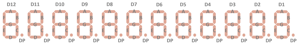
These Twelve-Digit Calculator Numeric Seven-Segment LED Displays are intended for use under pulsed conditions by enabling the common cathode of each digit sequentially and enabling the desired Segment and Decimal Point anodes in phase with the character enabling pulse. The pulse rate is kept high enough so that light from each character appears to the eye to be constant. The "G" segment of Digit 3 is accessible on a separate terminal to allow its use as the minus sign of the Exponent for scientific calculators based on the TMS0100 family of single-chip calculator circuits.
The DIS115 Twelve-Digit display assembly consists of a printed circuit board (PCB) with 12 individual DIS279 Seven-Segment displays and succeeds the CP-200032 Display-PCB introduced with the SR-10 Version 1 and based on the TIL360 Multi-Digit displays. While the DIS115 maintains the mechanical dimensions of the CP-200032, improves its increased spacing between the DIS279 elements and the integrated magnifying lens the readability of the 0.10”/2.54 mm characters significantly. The DIS115E was soon replaced with the DIS115F with 12 individual DISXXX Seven-Segment displays.
|
• 0.1”/2.54 mm Characters • Seven-Segment Digits with Right-Hand Decimals • Continuous Uniform Segments • Wide Viewing Angle • Common-Cathode Configuration for Multiplex Applications • 0.185”/4.7 mm Character Spacing • Integrated Clear Plastic Lens |
| Type | Products | Digits | Comments |
| DIS115E | SR-11 Version 1 | Segment G Digit 3 |
| Type | Products | Relationship | Comments |
| DIS288 | SR-50 | Relative | Uses 14*DIS279 |
| DIS134B | TI-2550 (Italy) | Relative | Uses 9*DIS279 |
| DIS115F | SR-10 Version 1, Display 2, SR-10 Version 2, SR-10 Version 3, SR-11 Version 1, Display 2 | Successor | Uses 12*DISXXX |
| Item | Min | Typ | Max | Unit | Comments |
| Display Width |
2.65 67.5 |
inch mm |
|||
| Display Height |
0.87 22.0 |
inch mm |
|||
| Display Depth |
0.26 6.7 |
inch mm |
Including Printed Circuit Board, without Pins |
||
| PCB Thickness |
0.03 0.8 |
inch mm |
|||
| Lens Width |
2.50 63.5 |
inch mm |
|||
| Lens Height |
0.36 9.2 |
inch mm |
|||
| Lens Depth |
0.23 5.9 |
inch mm |
|||
| Character Height |
0.100 2.54 |
inch mm |
At 0.4" / 10 mm Viewing
Distance w/o lens 0.080" / 2.00 mm |
||
| Character Width |
0.070 1.78 |
inch mm |
w/o Decimal Point w/o lens 0.055" / 1.42 mm |
||
| Character Slant Angle |
10 | degrees | |||
| Character Spacing |
0.185 4.70 |
inch mm |
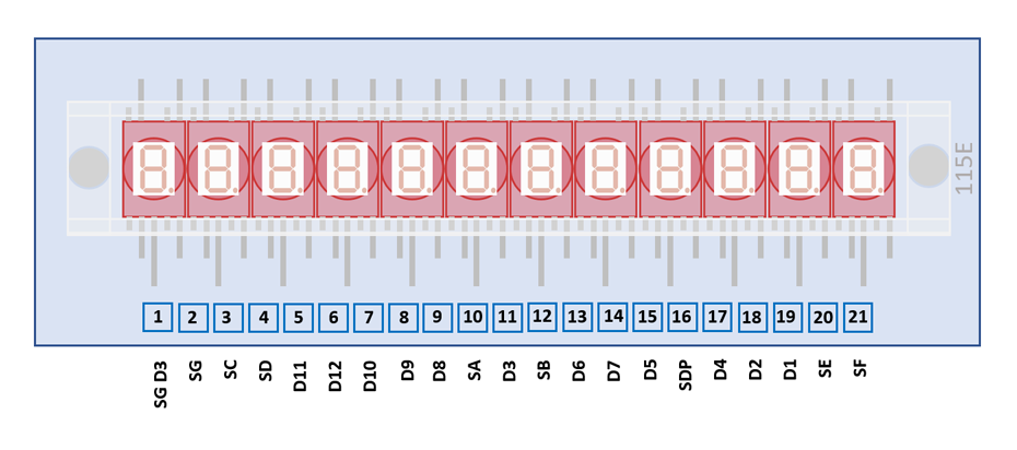
The displays are formed by soldering twelve individual DIS279 Seven-Segment displays on a double-sided printed circuit board (PCB) and placing a one-piece acrylic magnifying lens with cylindrical shape on top of the assembly with two heat stakes.
The DIS115E uses a 2.65" / 67.5 mm by 0.87” / 22.0 mm rectangular printed circuit board (PCB) with 21 solder tabs with a 0.1” / 2.54 mm pitch arranged on the bottom of the display module.
| Pin | Pol. | Function |
| 1 | A | G Segment Digit 3 (H) |
| 2 | A | G Segments Digits 1-2, 4-12 |
| 3 | A | C Segments |
| 4 | A | D Segments |
| 5 | C | Digit 11 (MSD Mantissa) |
| 6 | C | Digit 12 (Minus Sign) |
| 7 | C | Digit 10 |
| 8 | C | Digit 9 |
| 9 | C | Digit 8 |
| 10 | A | A Segments |
| 11 | C | Digit 3 (Minus Sign Exp.) |
| 12 | A | B Segments |
| 13 | C | Digit 6 |
| 14 | C | Digit 7 |
| 15 | C | Digit 5 |
| 16 | A | Decimal Points |
| 17 | C | Digit 4 (LSD Mantissa) |
| 18 | C | Digit 2 (MSD Exponent) |
| 19 | C | Digit 1 (LSD Exponent) |
| 20 | C | E Segments |
| 21 | C | F Segments |
| The Anode of the Segments A-G, Segment G (H) for minus sign of the Exponent and Right-Hand Decimals and the Cathode of the Digits 1-12 are connected to the display in the pictured way. |
 |
If you have additions to the above datasheet please email: joerg@datamath.org.
© Joerg Woerner, December 22, 2021. No reprints
without written permission.