DATAMATH CALCULATOR MUSEUM
|
DATAMATH CALCULATOR MUSEUM |
These Nine-Digit Calculator Numeric Seven-Segment LED Displays known as Bowmar Optostic are intended for use under pulsed conditions by enabling the common cathode of each digit sequentially and enabling the desired Segment and Decimal Point anodes in phase with the character enabling pulse. The pulse rate is kept high enough so that light from each character appears to the eye to be constant.
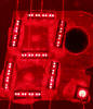
The R7H-122-9 Nine-Digit display assembly uses Chip-on-Board (COB) technology with each character formed by bonding seven individual Segment LED chips and one Decimal Point LED chip directly to a printed circuit board (PCB) and protecting them with a one-piece flat protection lens.
The leftmost character misses one segment and its decimal point and is typically used to display the minus sign of negative numbers, any number entry or calculating overflow conditions, and with some calculator chips as Memory indicator.
|
• 0.12”/3.0 mm Characters • Seven-Segment Digits with Right-Hand Decimals • Continuous Uniform Segments • Wide Viewing Angle • Common-Cathode Configuration for Multiplex Applications • 0.155”/3.9 mm Character Spacing • Integrated Red Plastic Lens • Optional Red Magnifying Lens |
| Type | Products | Digits | Comments |
| R7H-122-9 | Canon LE-81M, Heathkit IC-2009, Craig 4511, Kovac LE-808MR | ||
| R7H-122-9M | Interton PC 2008 | No R7H-122 marking | |
| R7H-122-9A | Bowmar MX20, MX25 | Magnifying Lens |
| Type | Products | Relationship | Comments |
| R7H-122-11 | Canon LE-100 | Relative | 11 digits |
| DIS114 | Relative | Different PCB | |
| DIS206A | Relative | Different PCB and Character spacing |
| Item | Min | Typ | Max | Unit | Comments |
| Display Width |
2.40 60.8 |
inch mm |
|||
| Display Height |
0.72 18.3 |
inch mm |
|||
| Display Depth |
0.15 3.8 |
inch mm |
Including Printed Circuit Board, without Pins |
||
| PCB Thickness |
0.06 1.6 |
inch mm |
FR4 | ||
| Lens Width |
1.70 43.2 |
inch mm |
|||
| Lens Height |
0.50 12.7 |
inch mm |
|||
| Lens Depth |
0.09 2.2 |
inch mm |
|||
| Character Height |
0.120 3.00 |
inch mm |
|||
| Character Width |
0.085 2.20 |
inch mm |
w/o Decimal Point | ||
| Character Slant Angle |
10 | degrees | |||
| Character Spacing |
0.155 3.94 |
inch mm |
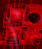
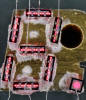
The displays are formed by bonding seven individual GaAsP (Gallium Arsenide Phosphide) Segment LED chips and one GaAsP Decimal Point LED chip per character directly to a double-sided FR4 printed circuit board (PCB) and placing a one-piece red acrylic protecting lens on top of the assembly with four heat stakes.
The die size of the Segment LED chip is approximately 42 mils * 13 mils / 1.1 mm * 0.3 mm, the die size of the Decimal Point LED chip is approximately 21 mils * 21 mils / 0.5 mm * 0.5 mm.
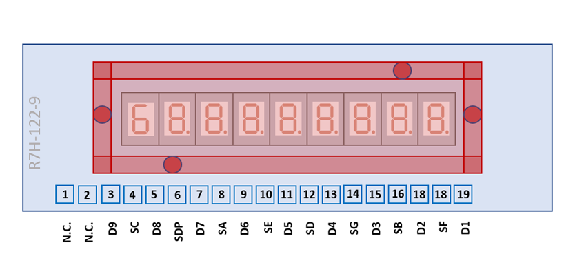
The R7H-122-9 uses a 2.40" / 60.8 mm by 0.72” / 18.3 mm rectangular printed circuit board (PCB) with 19 solder tabs with a 0.1” / 2.54 mm pitch arranged on the bottom of the display module.
The 19 solder tabs are either from circular or tear-drop shape.
| Pin | Pol. | Function |
| 1 | n.c. | |
| 2 | n.c. | |
| 3 | C | Digit 9 (Minus Sign) |
| 4 | A | C Segments |
| 5 | C | Digit 8 (MSD) |
| 6 | A | Decimal Points |
| 7 | C | Digit 7 |
| 8 | A | A Segments |
| 9 | C | Digit 6 |
| 10 | A | E Segments |
| 11 | C | Digit 5 |
| 12 | A | D Segments |
| 13 | C | Digit 4 |
| 14 | A | G Segments |
| 15 | C | Digit 3 |
| 16 | A | B Segments |
| 17 | C | Digit 2 |
| 18 | A | F Segments |
| 19 | C | Digit 1 (LSD) |
| The Anode of the Segments A-G and Right-Hand Decimals and the Cathode of the Digits 1-9 are connected to the display in the pictured way. |
 |
If you have additions to the above datasheet please email: joerg@datamath.org.
© Joerg Woerner, January 2, 2022. No reprints
without written permission.