DATAMATH CALCULATOR MUSEUM
|
DATAMATH CALCULATOR MUSEUM |
Understanding that sooner or later the complete portfolio of electronic calculators and educational products needs to be ported from power-hungry LED- and VF-Displays to LC-Displays, Texas Instruments initiated in 1978 together with the development of the TI Programmable 59 successor, dubbed "Project X", a very ambitious project called "LCD III". Main objective of this project was the replacement of all existing calculator chips used within the broad spectrum of basic four-function calculators to high-end programmable calculators and educational toys with a family of just three chip sizes A, B, and C, differing mainly in ROM and RAM capacity and each chip optionally including additional modules for timekeeping functions and drivers for LC-Displays.
Looking into the advantages and disadvantages of the two architectures in use, Register Processors and Digit Processors, and already experienced with porting the TMS1000 microcontroller-based TI-30 calculator chip TMC0980 to CMOS technology for the TI-50 resulting in the TP0320 chip, Texas Instruments decided to combine the speed of Register Processors with the flexibility of Digit Processors with introducing not only a so-called Fast-ROM with 13-bit width to the normal instructions ROM but switching from a metal gate CMOS process to a more advanced polysilicon gate CMOS process.
The chips were defined as follows:
|
• Chip A replaces TMC1000, TMC0970, TMC1990, TMC0920, TP0310 • Chip B replaces TMC0980, TMC1980, TMC1100, TP0320 • Chip C replaces TMC1500 |
Each chip was meant to be more powerful than the chip it replaces with Chip B a subset of Chip C and Chip A a subset of Chip B.
History tells us the Texas Instruments did not meet these demanding goals and the only application of an LCD III chip is the TP0485 used with the cancelled TI Programmable 88 calculator. However did the work on LCD III influence future calculator chips, the TP0455/TP0456 design inherited the optional chip-to-chip communication with a 4-bit I/O port and the optional module for timekeeping functions while the TP0458 design made use of the scalability of ROM and RAM capacity.
The polysilicon gate CMOS process had a great comeback with the TMC70C20 8-bit single-chip microcontroller family used with the Compact Computer 40 and many other TI Consumer Products.
The TP0470/TP0475/TP0480/TP0485 chip includes 41,600 Bits Read-Only Memory (ROM 3k*13 Bits, Fast ROM 128*13 Bits) and 1,408 Bits Random-Access Memory (RAM, 22 Registers * 16 Digits), a 4-bit Arithmetic unit, timekeeping functionality with a 32.768 kHz crystal (TP0475/TP0485 only), an high-speed oscillator for a 1.6 MHz Master Clock, a 4-bit I/O bus for processor-to-processor communication and external memory expansion, an 1-bit I/O bus for calculator-to-calculator or calculator-to-peripheral communication, a programmable PLA for segment decoding and both segment and digit multiplexing for a 12-digit LC-Display with up to 84 segments and 4 common scan lines (TP0480/TP0485 only). A newly developed feature allowed most pins to be assigned either Input or Output functionality to allow easy “piggy backing” of multiple TP0485 chips communicating through the 4-bit I/O bus including a 4-wire handshake protocol.
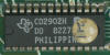
Early iterations of the TI Programmable 88 called "Product 225 - TI-85" used three LCD III chips the final design consolidated into two chips packaged in different sized housings with the larger CD2901 chip responsible for Timekeeping, Keyscan, and I/O and the smaller CD2902 chip interfacing with external memory and providing the Learn mode. A similar approach could be found with the Primary-Secondary architecture introduced with the TI-55-II based on two TP0455/TP0456 chips.
| Type | Calculator/Product | Application | Comments |
| TP0470/CD2902 | Product 225 - TI-85 (November, 1979) |
Programmable | ROM code CD2902, Primary Controller |
| TP0470/CD2903 | Product 225 - TI-85 (November 23, 1979) |
Programmable | ROM code CD2903, Arithmentic Controller |
| TP0475/CD2901 | Product 225 - TI-85 (November 23, 1979, February 1, 1980) |
Programmable | ROM code CD2901, Timekeeping, Keyscan, I/O Controller |
| TP0475/CD2902 | Product 225 - TI-85 (February 1, 1980) |
Programmable | ROM code CD2902, Primary Controller |
| TP0485/CD2901 | Product 225 - TI-88 (March 12, 1980) |
Programmable | ROM code CD2901, Timekeeping, Keyscan, I/O Controller |
| TP0485/CD2902 | Product 225 - TI-88 (March 12, 1980) |
Programmable | ROM code CD2902, Primary Controller |
| Description | Comments | |
| Architecture | Single-chip Calculator | Scientific, Programmable |
| Category | Digit Processor | 4-bit Digits |
| Related | ||
| ROM Size | 41,600 Bits | 3072 Words * 13 Bits + 128 Words * 13 Bits Fast RP< |
| RAM Size | 1,408 Bits | 22 Registers * 16 Digits 64 Bits Display Register |
| Outputs | 4 Common, 21 Segments | Integrated Common Scan Line and Segment Drivers (not used with TI-88) |
| Inputs | 5 Keyboard | Segment to Keyboard Scan-Matrix |
| Miscellaneous | 4-bit I/O Port,
4-wire Handshake 1-bit I/O Port 32.768 kHz Timekeeping High-speed Clock |
MCU-to-MCU, MCU to ext. Memory Calculator-to-Calculator/Peripheral External Crystal 1.6 MHz Master Clock |
| Item | Min | Typ | Max | Unit | Comments |
| VCC | 3.0 | V | |||
| GND | 0 | V | |||
| CK | 1,600 | kHz | Internal oscillator |
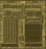
The TP0470/TP0475/TP0485 were manufactured in a 5 um silicon gate CMOS process (metal width = 0.20 mil / 5.0 um, metal spacing = 0.20 mil / 5.0 um, diffusion width = 0.20 mil / 5.0 um, diffusion spacing = 0.20 mil / 5.0 um).
The die size of the TP0485 is approximately 220 mils * 220 mils / 5.6 mm * 5.6 mm.
The TP0470/TP0475/TP0485 uses either a 0.6” wide 40-pin SPDIP (Plastic Dual In-line Package with a 0.07” / 1.778 mm lead pitch)
or a 0.4” wide 28-pin SPDIP (Shrink Plastic Dual In-line Package with a 0.07” / 1.778 mm lead pitch).
TP0485/CD2901 (TI Programmable 88)
| Pin | IO | Function | Pin | IO | Function |
| 1 | I | OSC-IN 32.768 kHz | 40 | IO | IO1 |
| 2 | O | OSC-OUT 32.768 kHz | 39 | IO | IO2 |
| 3 | O | OSC-TP 8.192 kHz | 38 | IO | IO8 |
| 4 | O | R29 (Piezo) | 37 | IO | IO8 |
| 5 | O | R28 Key row 9 | 36 | O | R15 Data to P |
| 6 | I | KE Key input 3 | 35 | I | KH Low Battery Indicator |
| 7 | O | R1 Key row 2 | 34 | O | R9 Interrupt |
| 8 | O | R4 Key row 3 | 33 | I | KF Ready |
| 9 | I | KC Key input 2 | 32 | O | R10 Request |
| 10 | O | R12 Key row 5 | 31 | I | KG Request |
| 11 | O | R8 Key row 4 | 30 | O | R11 Ready |
| 12 | I | KD Key input 4, OFF | 29 | O | R2 Display Data |
| 13 | O | R20 Key row 7 | 28 | O | R6 Display Clock |
| 14 | O | R24 Key row 8 | 27 | IO | PIO Data from Peripheral |
| 15 | I | KA Key input 5, ON | 26 | O | R3 Display Control |
| 16 | O | R16 Key row 6 | 25 | n.c. | |
| 17 | O | R0 Key row 1 | 24 | n.c. | |
| 18 | I | KB Key input 1 | 23 | I | Test-CLK (GND) |
| 19 | V | VCC Positive Voltage | 22 | O | HS-CLK 1.6 MHz Out |
| 20 | V | GND Ground | 21 | I | TEST (GND) |
| Pin | IO | Function | Pin | IO | Function |
| 1 | O | R0 CS0 | 28 | IO | IO1 |
| 2 | O | R2 CS2 | 27 | IO | IO2 |
| 3 | O | R3 CS3 | 26 | IO | IO8 |
| 4 | O | R7 CS7 | 25 | IO | IO8 |
| 5 | O | Do not connect | 24 | I | Do not connect |
| 6 | O | R5 CS5 | 23 | O | Do not connect |
| 7 | O | R4 CS4 | 22 | I | Do not connect |
| 8 | I | KA Interrupt | 21 | O | R1 CS1 |
| 9 | O | R14 Ready | 20 | O | R6 CS6 |
| 10 | I | KB Request | 19 | O | Do not connect |
| 11 | O | R15 Request | 18 | O | LS-CLK 267 kHz Out |
| 12 | I | KE Ready | 17 | I | Test-CLK (GND) |
| 13 | V | VCC Positive Voltage | 16 | I | HS-CLK 1.6 MHz In |
| 14 | V | GND Ground | 15 | I | TEST (GND) |
The keyboard of the TI Programmable 88 consist of an x/y-matrix connected to 9 R-Outputs and the keymatrix inputs KA, KB, KC, KD, and KE. A 3-Position (momentary-locking-momentary) slide switch connects ON and OFF to keymatrix inputs KA and KD respectively.
Example for the TI Programmable 88 with TP0485/CD2901:
| KB | KC | KE | KD | KA | |
| R0 | YES | NO | UNK | ENT | CONT |
| R1 | EQN | EVAL | # | OP | 2nd |
| R4 | PGM | ( )-1 | STO | RCL | INV |
| R8 | SBR | ( )N | ↑ | ↓ | ALPH |
| R12 | GTO | EE | ( | ) | ÷ |
| R16 | → | 7 | 8 | 0 | × |
| R20 | ← | 4 | 5 | 6 | − |
| R24 | R/S | 1 | 2 | 3 | + |
| R28 | CE/C | 0 | . | +/− | = |
Calculators based on the TP0485 could make use of 12-digit LCDs (Liquid-Crystal-Displays) with 4 COM (common scan) lines but the TI Programmable 88 didn't make use of the internal display drivers and used two TP0530 cascadable display drivers, instead.
If you have additions to the above datasheet please email: joerg@datamath.org.
© Sean Riddle and Joerg Woerner, January 14, 2021. No reprints
without written permission.