DATAMATH CALCULATOR MUSEUM
|
DATAMATH CALCULATOR MUSEUM |
With the TMS1802NC Texas Instruments announced on September 17, 1971 the first available standard calculator building block on a chip, it was later renamed into TMS0102. The chip integrates 3520-bit Read-Only program memory, a 182-bit Serial-Access memory and a decimal arithmetic logic unit as well as control, timing, and output decoders but no drivers for the display. This gives an overall complexity of roughly 5,000 transistors.
Due to a flexible design concept with both programmable PLA and ROM techniques a lot of design variations appeared. These include two different types of the key-matrix, 8 or 10 digits of 7- or 8-segmented outputs. Even the style of the numbers 4,6 and 9 varied among the family members.
Based on the experience of the TMS0120 developed for the SR-10 some fully floating-point devices derived from the TMS0106 were developed.
| Type | Calculators | Key-Matrix | Digits | Segment decoder | Timing |
| TMS0123 | [+=],[-=] | 10 | LED | ||
| TMS0126 | Canon LE-80R, Commodore 3101, Privileg 820 | [+=],[-=] | 8 | LED | |
| TMS0127 | Bowmar MX-80 | [+=],[-=] | 10 | LED | |
| TMS0128 | Canon LE-82, JCE Percent, Montgomery Ward P8P, Western Auto M4995 | [+=],[-=] | 8 | LED |
| Item | Min | Typ | Max | Unit | Comments |
| VSS | 0 | V | |||
| VDD | -8.1 | -7.2 | -6.6 | V | |
| VGG | -13.2 | -14.4 | -16.2 | V | |
| IDD | 17 | 25 | mA | ||
| IGG | 10 | 15 | mA | ||
| CK | 100 | 250 | 400 | kHz | Level between VSS and VGG |
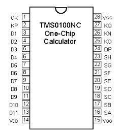
The TMS0123 uses a standard 0.6” wide 28-pin DIP (Dual In-line Package with a 0.1” / 2.54 mm lead pitch).
| Pin | IO | Function | Pin | IO | Function |
| 1 | I | Clock Input | 28 | V | Common Voltage |
| 2 | I | Keymatrix input P | 27 | I | Keymatrix input Q |
| 3 | O | Digit driver 1 (LSD) | 26 | I | Keymatrix input N |
| 4 | O | Digit driver 2 | 25 | I | Keymatrix input O |
| 5 | O | Digit driver 3 | 24 | O | Segment driver DP |
| 6 | O | Digit driver 4 | 23 | O | Segment driver H |
| 7 | O | Digit driver 5 | 22 | O | Segment driver G |
| 8 | O | Digit driver 6 | 21 | O | Segment driver F |
| 9 | O | Digit driver 7 | 20 | O | Segment driver E |
| 10 | O | Digit driver 8 (MSD8) | 19 | O | Segment driver D |
| 11 | O | Digit driver 9 | 18 | O | Segment driver C |
| 12 | O | Digit driver 10 (MSD10) | 17 | O | Segment driver B |
| 13 | O | Digit driver 11 (OVER) | 16 | O | Segment driver A |
| 14 | V | Negative Voltage VDD | 15 | V | Negative Voltage VGG |
| The Segment drivers A-G/H and DP (Decimal Point) are connected to the display in the pictured way. | 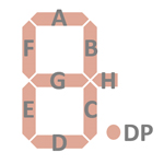 |
The keyboards of all calculators based on the TMS0102 family consist of a x/y-matrix connected to the digit driver outputs D1-D11 and the key-matrix inputs KN and KO. In the fixed-point output format mode the position of the decimal point is selected with the KP input. The Constant/Chain switch is connected between D10-KQ.
TMS0123, 0126 |
TMS0127, 0128 |
||||||||
| KN | KO | KP | KQ | KN | KO | KP | KQ | ||
| D1 | 1 | x2 | D1 | 1 | 0/00 | DP1 | |||
| D2 | 2 | * | D2 | 2 | * | DP2 | |||
| D3 | 3 | : | D3 | 3 | : | DP3 | |||
| D4 | 4 | srqX | D4 | 4 | % | DP4 | |||
| D5 | 5 | += | D5 | 5 | += | DP5 | |||
| D6 | 6 | -= | D6 | 6 | -= | DP6 | |||
| D7 | 7 | +/- | D7 | 7 | 00 | DP7 | |||
| D8 | 8 | D8 | 8 | A/D | (DP8) | ||||
| D9 | 9 | . | D9 | 9 | . | (DP9) | |||
| D10 | 0 | CE | K | D10 | 0 | CE | DP0 | K | |
| D11 | C | D11 | C | ||||||
Calculators based on the TMS0102 use all kinds of displays. Texas Instruments introduced together with the calculator chip two pre-configured LED-modules (DIS40, DIS95) based on the TIL360 arrays, the corresponding segment drivers (SN75491) and digit drivers (SN75492). Most designs make use of these parts.
If you have additions to the above datasheet please email: joerg@datamath.org.
© Joerg Woerner, February 02, 2001. No reprints
without written permission.