DATAMATH CALCULATOR MUSEUM
|
|
DATAMATH CALCULATOR MUSEUM |
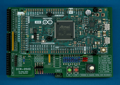
Datamath Calculator Museum TMS0500 8-Channel Serial Data Recorder
| Date of introduction: | January 15, 2024 | Display technology: | |
| New price: | $1,049.95 (2022 = $169.95 in 1974) | Display size: | |
| Size: | 3.2" x 4.8" x 1.1" 81 x 122 x 28 mm3 |
||
| Weight: | 2.8 ounces, 79 grams | Serial No: | 0001 |
| Batteries: | Date of manufacture: | mth 01 year 2024 | |
| AC-Adapter: | DC 5V (USB) | Origin of manufacture: | USA |
| Precision: | Integrated circuits: | Arduino DUE | |
| Memories: | 96k Bytes SRAM, 512k Bytes Flash ROM | Displays: | |
| Program steps: | 8M Bits Serial SRAM | Courtesy of: | Joerg Woerner |
![]()
 The
TMS0500 8-Channel Serial Data Recorder is part of the modular DCM-0500
(Platform) to allow
Reverse-engineering of Calculators based on the TMS0500 Building Blocks
for Scientific and Programmable Calculators and Recording of
ROM Images of the Integrated Circuits (ICs) used with these calculators and connects to the
East-Port of the
TMS0500 ROM Platform.
The
TMS0500 8-Channel Serial Data Recorder is part of the modular DCM-0500
(Platform) to allow
Reverse-engineering of Calculators based on the TMS0500 Building Blocks
for Scientific and Programmable Calculators and Recording of
ROM Images of the Integrated Circuits (ICs) used with these calculators and connects to the
East-Port of the
TMS0500 ROM Platform.
The TMS0500 8-Channel Serial Data Recorder is basically a carrier for an Arduino UNO Platform and its user interface.
In the process of Reverse-engineering of Calculators the TMS0500 Building Blocks two modules are connected to the East-Port of the TMS0500 ROM Platform:
|
• Bottom:
TMS0500 8-Channel Serial Data Recorder 128-Bit Module • Top: TMS0500 8-Channel Serial Data Recorder with Arduino DUE |
The first module is used to de-serialize the relevant signals from the calculator under investigation into parallel 16-bit words and makes them available to the Arduino DUE of the second module running "TMS0500 DATA Recorder" Software to capture and log the information from the IRG and EXT signals and the I/O Bus and listing them it in a human readable form in a terminal window.
In the process of Recoding of ROM Images of the various ROM Chips of the TMS0500 Building Blocks the same configuration is extended by the TMC0501/TMC0501E Emulator connected to the West-Port of the TMS0500 ROM Platform running to stimulate the ROMs and Arduino DUE is running software to to convert the ROM responses into actual ROM listing.
The user interface of the TMS0500 8-Channel Serial Data Recorder is rather simple, a 16-position rotary switch selects the desired program, a green [INIT] button starts it and a red [STOP] button resets the system. The "Recording" in the "TMS0500 ROM Recorder" Software includes the first 10 position of the rotary switch and the "TMS0500 DATA Recorder" Software the next 3 positions:
|
• 0-7: Record First ROM Bank
0 to 7 of the TMS0500 Building Blocks (1,024 13-bit Instruction Words,
each) • 8: Record Second ROM of the TMS0500 Building Blocks (5,000 2-digit BCD Keycodes) • 9: Record Constant ROM of the TMS0500 Building Blocks (8*16 16-digit Constants) • A: Trace ALL (Store all information recorded on IRG, EXT and I/O Bus) • B: Trace TRG (Store information recorded on IRG, EXT and I/O Bus after trigger conditions are met) • C: Trace TRG+ (Store information recorded on IRG, EXT and I/O Bus before and after trigger conditions are met) |
A green [POWER] LED signals the status of the internal 5 Volt supply, a red LED [RECORD] LED signals the status of the Arduino DUE software and an amber [STREAM] LED signals a handshake with a possibly connected TMC0501/TMC0501E Emulator.
For more demanding applications, or when stacking more than one TMS0500 8-Channel Serial Data Recorder 128-Bit Modules, the TMS0500 8-Channel Serial Data Recorder Pro adds some oomph to the specifications.
If you have additions to the above article please email: joerg@datamath.org.
©© Joerg Woerner, January 7, 2024. No reprints without written permission.