DATAMATH CALCULATOR MUSEUM
|
|
DATAMATH CALCULATOR MUSEUM |
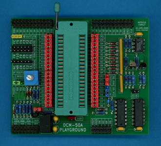
Datamath Calculator Museum DCM-50A Playground MK6010 Family Adapter
| Date of introduction: | March 29, 2025 | Display technology: | n.a. |
| New price: | Display size: | n.a. | |
| Size: | 3.2" x 4.0" x
0.85" 81 x 102 x 22 mm3 |
||
| Weight: | 2.9 ounces, 81 grams | Serial No: | 0001 |
| Batteries: | n.a. | Date of manufacture: | mth 04 year 2025 |
| AC-Adapter: | n.a. | Origin of manufacture: | USA |
| Precision: | Integrated circuits: | ZIF-24 Socket, 2*CD4066, CD40106, SN75369 | |
| Memories: | |||
| Program steps: | Courtesy of: | Joerg Woerner |
![]()
 Nippon Calculating Machine Corp of Japan, better known under their brand Busicom, tasked in Summer 1970 Mostek in Dallas, Texas to squeeze the electronics of their Model 120-DM, also known as Busicom Junior, into an LSI (Large Scale Integration) PMOS (p-channel Metal–oxide Semiconductor) chip. The resulting
MK6010 is widely recognized as the World’s first
"single-chip calculator circuit" and paved the way for the incredible LE-120A calculator, credited with many
"Firsts":
Nippon Calculating Machine Corp of Japan, better known under their brand Busicom, tasked in Summer 1970 Mostek in Dallas, Texas to squeeze the electronics of their Model 120-DM, also known as Busicom Junior, into an LSI (Large Scale Integration) PMOS (p-channel Metal–oxide Semiconductor) chip. The resulting
MK6010 is widely recognized as the World’s first
"single-chip calculator circuit" and paved the way for the incredible LE-120A calculator, credited with many
"Firsts":
| • First truly pocket-sized electronic calculator • First hand-held calculator using a single-chip calculator circuit • First use of an LED (Light-Emitting Diode) display with an electronic calculator • First calculator operated with disposable batteries |
The Busicom Junior, a small desktop calculator with a 12-digit Vacuum Fluorescent Display (VFD), was highly optimized for minimum component count and using 22 Integrated Circuits in JMOS technology from Mitsubishi, NEC and Toshiba, complemented by around 220 discrete diodes and more than 100 resistors.
The first working samples of the MK6010 were manufactured in November 1970 and the resulting chip is integrating more than 2,100 transistors in 360 gates plus 160 flip-flops and measures around 170 mils * 185 mils / 4.3 mm * 4.7 mm. With the goal to keep many parts of the Busicom Junior untouched while replacing its two large PCBs with a smaller one, the MK6010 inherited consequently many features from the original logic design:
| • Two power supply rails, VDD = -12 V and VGG = -24 V • Two-phase clock with 25 kHz nominal frequency • Negative logic for keyboard inputs • BCD-encoded numeral inputs with "Zero" encoded as 'BCD 1010' or "Ten" with "No Key" encoded as 'BCD 0000' • Negative logic of Digit and Segment outputs for easy interfacing to low-voltage VFDs • Fix-point arithmetic with decimal point set at position 0, 2, 3, or 4 |
Later single chip calculators chips, like the groundbreaking TMS0100 Product Family introduced in September 1971, traded minimum transistor count for maximum flexibility. With the TMS0100 serving as blueprint for many other calculator chips, the DCM-50A Platform and its extension DCM-50A (PLAYGROUND) are perfectly suited to cover most calculator chips developed in the early 1970s. On our quest to document Mostek's MK6010 and its many descendants, we developed here at the Datamath Calculator Museum three additional tools for our DCM-50A (PLAYGROUND):
| • DCM-50A (PLAYGROUND)
MK6010 Family Adapter: Daughter Board for
Mostek's MK6010/MK5010 and Cal-Tex's CT5001/CT5012 Portfolio • DCM-50A (PLAYGROUND) Digit Inverter Frame Carrier: Plug-In Carrier to access all voltages and signals of the DCM-50A Platform for Chips with Inverted Inputs/Outputs • DCM-50A (PLAYGROUND) KBD102 Keyboard: Keyboard with 20 individual keys and 4-bit BCD-Encoded input port for the numbers and individual keys for the functions |
To access all features of the early MK6010 Chips, the schematics and layout of the DCM-50A Playground MK6010 Family Adapter are providing accordingly:
| • DC/DC Converter for high-voltage
MK6010 Chips • Selector Jumper for high-voltage (24 V) or low-voltage (6...15 V) Chips • 3 green LEDs to signal VDD, VGG(LV) and VGG(HV) voltages • Red LED for MK6010 "Sign Output" • Header Pins for all DCM-50A Platform Signals provided by the DCM-50A PG Digit Inverter Frame • Two-phase 25 kHz Clock Oscillator, Selector Jumper for internal/external Oscillator and Level-Shifter • Connector to KBD102 Keyboard • 4-Position Rotary Switch to select Decimal Point Position 0, 2, 3, or 4 • Optional wiring for full 12-digit output • Header Pins for various MK6010 Signals • Patch Field for all 40 pins of the MK6010 Chip |
 Please notice that the DCM-50A PG
MK6010 Family Adapter needs to be
mounted on top of the DCM-50A PG Digit Inverter Frame
Carrier.
Please notice that the DCM-50A PG
MK6010 Family Adapter needs to be
mounted on top of the DCM-50A PG Digit Inverter Frame
Carrier.
The Cal-Tex CT5002 Chip and its sibling Litronix
LIT-019 were optimized for battery-operated calculators sporting LED displays
and need multiple tweaks to be operated with the DCM-50A PG MK6010 Family
Adapter:
| • DCM-50A PG MK6010 Family Adapter mounted on top of the
DCM-50A PG Frame Carrier (Non-inverting Digit and Segment Outputs) • Selector Jumper for set to low-voltage (6...15 V) Chips (6 V Supply) • CK1 and CK2 Jumpers at CT5002 removed and CT5002 Pins connected to DIN21 and DIN22 Pins (CK1 and CK2 Out Load Resistors) • VGG Jumper at CT5002 removed and CT5002 Pin connected to CK1 Pin (Clock Input) • SH Jumper at CT5002 removed and CT5002 Pin connected to VDD (Display Enable Input) • SIGN Jumper at CT5002 and SIGN POL Jumper removed and CT5002 Pin connected to right Pin of SIGN POL Jumper (Sign Polarity) |
If you have additions to the above article please email: joerg@datamath.org.
© Joerg Woerner, December 7, 2025. No reprints without written permission.