DATAMATH CALCULATOR MUSEUM
|
DATAMATH CALCULATOR MUSEUM |
These Nine-Digit Calculator Numeric Seven-Segment LED Displays are intended for use under pulsed conditions by enabling the common cathode of each digit sequentially and enabling the desired Segment and Decimal Point anodes in phase with the character enabling pulse. The pulse rate is kept high enough so that light from each character appears to the eye to be constant.
The DIS134C Nine-Digit display assembly consists of a printed circuit board (PCB) with 9 individual DISXXX Seven-Segment displays and was introduced in August 1973 with the TI-2500 Version 3 to replace the earlier display assemblies based on the TIL360 Multi-Digit displays. The increased spacing between the DISXXX elements and the integrated magnifying lens improved the readability of the 0.1”/2.54 mm characters significantly compared to the TI-2500 Version 2.
|
• 0.1”/2.54 mm Characters • Seven-Segment Digits with Right-Hand Decimals • Continuous Uniform Segments • Wide Viewing Angle • Common-Cathode Configuration for Multiplex Applications • 0.200”/5.1 mm Character Spacing • Integrated Clear Plastic Lens |
| Type | Products | Digits | Comments |
| DIS134C | TI-2500 Version 3, TI-2550 Version 1 |
| Type | Products | Relationship | Comments |
| DIS134B | TI-2550 (Italy) | Predecessor | Uses 9*DIS279 |
| DIS288 | SR-50 | Pre-Relative | Uses 14*DIS279 |
| DIS115F |
SR-10 Version 1, Display 2, SR-11 Version 1, Display 2 |
Relative | Uses 12*DISXXX |
| DIS206A | TI-2550 Version 1, Display 2 | Successor | Uses Bowmar Optostic |
| Item | Min | Typ | Max | Unit | Comments |
| Display Width |
2.50 63.5 |
inch mm |
|||
| Display Height |
1.02 26.0 |
inch mm |
|||
| Display Depth |
0.26 6.6 |
inch mm |
Including Printed Circuit Board, without Pins |
||
| PCB Thickness |
0.03 0.8 |
inch mm |
|||
| Lens Width |
2.10 53.3 |
inch mm |
|||
| Lens Height |
0.38 9.7 |
inch mm |
|||
| Lens Depth |
0.23 5.8 |
inch mm |
|||
| Character Height |
0.100 2.54 |
inch mm |
|||
| Character Width |
0.070 1.78 |
inch mm |
w/o Decimal Point | ||
| Character Slant Angle |
10 | degrees | |||
| Character Spacing |
0.200 5.08 |
inch mm |
The displays are formed by soldering twelve individual DISXXX Seven-Segment displays on a double-sided printed circuit board (PCB) and placing a one-piece acrylic magnifying lens with cylindrical shape on top of the assembly with two heat stakes.
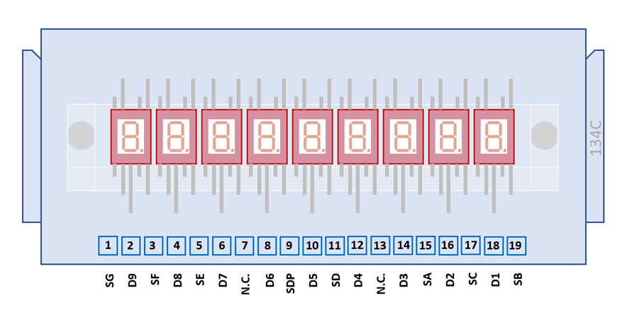
The DIS134C uses a 2.50" / 63.5 mm by 1.02” / 26.0 mm rectangular printed circuit board (PCB) with 19 solder tabs with a 0.1” / 2.54 mm pitch arranged on the bottom of the display module.
| Pin | Pol. | Function |
| 1 | A | G Segments |
| 2 | C | Digit 9 (Minus Sign) |
| 3 | A | F Segments |
| 4 | C | Digit 8 (MSD) |
| 5 | A | E Segments |
| 6 | C | Digit 7 |
| 7 | n.c. | |
| 8 | C | Digit 6 |
| 9 | A | Decimal Points |
| 10 | C | Digit 5 |
| 11 | A | D Segments |
| 12 | C | Digit 4 |
| 13 | n.c. | |
| 14 | C | Digit 3 |
| 15 | A | A Segments |
| 16 | C | Digit 2 |
| 17 | A | C Segments |
| 18 | C | Digit 1 (LSD) |
| 19 | A | B Segments |
| The Anode of the Segments A-G, Segment G (H) for minus sign of the Exponent and Right-Hand Decimals and the Cathode of the Digits 1-9 are connected to the display in the pictured way. |
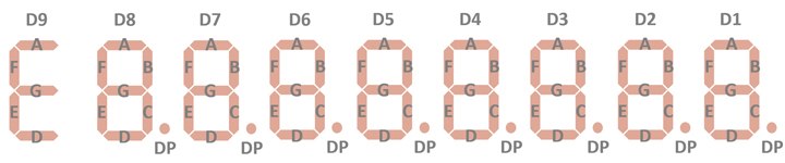 |
Note: The DIS134C Display module has the pins of Segment B, Segment C and Decimal Point (Segment DP) of the leftmost digit cut.
If you have additions to the above datasheet please email: joerg@datamath.org.
© Joerg Woerner, November 28, 2021. No reprints
without written permission.