DATAMATH CALCULATOR MUSEUM
|
DATAMATH CALCULATOR MUSEUM |
Texas Instruments introduced the short-lived TMC0920 Product Family of single-chip calculator circuits in June 1977 with the two basic calculators TI-1025 and TI-1050. Within just one year Texas Instruments introduced with the TI-1030 and TI-1070 calculators with a similar feature set in a much smaller housing and powered by two small button style alkaline batteries good for more than 1,000 hours of operation time. This tremendous progress was made possible by replacing the power-hungry LED Display with an LC-Display and switching the manufacturing process of the single-chip calculator circuit from a 9V metal gate PMOS process to a 3V metal gate CMOS process. The TP0310 family is based on the highly cost-optimized TMC0920 design, in contrast to the Digit Processor architecture used with the TP0320, continues the TP0310 the Register Processor approach known from the TMS0100 family introduced already in November 1971 with the famous TMS1802 chip. The TP0310 chip includes 4,608 Bits Read-Only Memory (ROM, 512*9 Bits – only 511 Words accessible due to the design of the program counter) and 200 Bits Serial-Access Memory (SAM, 4 Registers * 10 Digits), 40 Bits Display, a 4-bit Arithmetic unit, a programmable PLA for segment decoding and both segment and digit multiplexing for a 9-digit LC-Display with up to 67 segments and 3 common scan lines.
Due to a flexible design concept with a programmable ROM but fixed segment decoder some design variations appeared.
| Type | Calculator/Product | Application | Comments |
| TP0311 | E.T. Calculator, TI-1001, TI-1010, TI-1030, TI-1031, TI-1032, TI-1040, TI-1750 III, TI-1850, TI-1880 | Basic | 4-key Memory, srq(x), % |
| TP0314 | TI-1070, TI-1071 | Basic | Memory, x2, 1/x, sqr(x), PI |
| Description | Comments | |
| Architecture | Single-chip Calculator | Basic |
| Category | Register Processor | BCD-serial |
| Related | TMC0920 | PMOS, 7-segment LED-Display |
| ROM Size | 4,608 Bits | 512 Words * 9 Bits |
| SAM Size | 200 Bits | 5 Registers * 10 Digits |
| Outputs | 3 Common, 22 Segments | Integrated Common Scan Line and Segment Drivers |
| Inputs | 4 Keyboard | Segment to Keyboard Scan-Matrix |
| Item | Min | Typ | Max | Unit | Comments |
| VDD | 3.0 | V | |||
| VSS | 0 | V | |||
| CK | 250 | 350 | 450 | kHz | Internal oscillator |
The TP0310 was manufactured in a 5 um metal gate CMOS process (metal width = 0.20 mil / 5.0 um, metal spacing = 0.25 mil / 6.0 um, diffusion width = 0.20 mil / 5.0 um, diffusion spacing = 0.20 mil / 5.0 um).
The die size of the TP0310 is approximately 135 mils * 150 mils / 3.4 mm * 3.8 mm.
The TP0310 uses a 0.4” wide 28-pin SPDIP (Shrink Plastic Dual In-line Package with a 0.07” / 1.778 mm lead pitch).
| Pin | IO | Function | Pin | IO | Function |
| 1 | IO | Key row 1, DP8, C8, B8 | 28 | O | Segments D6, G6, A6 |
| 2 | IO | Key row 3, D8, E7, F7 | 27 | O | Segments DP6, C6, B6 |
| 3 | IO | Key input 2, D7, G7, A7 | 26 | h.c. | |
| 4 | IO | Key row 2, DP7, C7, B7 | 25 | O | Segments G8, E5, F5 |
| 5 | IO | Key row 4, E8, E6, F6 | 24 | O | Segments D5, G5, A5 |
| 6 | IO | Key input 3, DP2, C2, B2 | 23 | O | Segments DP5, C5, B5 |
| 7 | IO | Key row 5, A8, E1, F1 | 22 | O | Segments F8, E4, F4 |
| 8 | IO | Key row 6, D1, G1, A1 | 21 | O | Segments D4, G4, A4 |
| 9 | IO | Key input 4, DP1, C1, B1 | 20 | O | Segments DP4, C4, B4 |
| 10 | V | Negative Voltage VSS | 19 | O | Segments, M, E3, F3 |
| 11 | VI | Key input 1, VDD | 18 | O | Segments D3, G3, A3 |
| 12 | O | LCD COM 1 | 17 | O | Segments DP3, C3, B3 |
| 13 | O | LCD COM 2 | 16 | O | Segments SIGN, E2, F2 |
| 14 | O | LCD COM 3 | 15 | O | Segments D2, G2, A2 |
| The Segment drivers A-G and DP (Decimal Point) are connected to the display in the pictured way. | 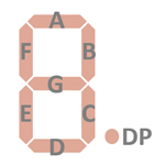 |
The keyboards of all calculators based on the TP0310 Product Family consist of an x/y-matrix connected to up to six digit outputs outputs and the keymatrix inputs K1, K2, K3, and K4 with the left column ([ON] key) connected to VDD.
Example for the TI-1030 with TP0311:
| VDD K1 | K2 | K3 | K4 | |
| Row 6 | MC | MR | M- | M+ |
| Row 5 | OFF | √x | % | ÷ |
| Row 4 | 7 | 8 | 9 | × |
| Row 3 | 4 | 5 | 6 | − |
| Row 2 | 1 | 2 | 3 | + |
| Row 1 | On/C | 0 | . | = |
Calculators based on the TP0310 make use of 9-digit LCDs (Liquid-Crystal-Displays) with 3 COM (common scan) lines. The battery indicator is connected between LCD COM 2 and LCD COM 3.
If you have additions to the above datasheet please email: joerg@datamath.org.
© Sean Riddle and oerg Woerner, January 124 2021. No reprints
without written permission.